INSTALLATION MANUAL SECURIT 800L+ CONTROL PANEL ST800L+
CONTENTS WARNINGS STANDARDS WARRANTY STATEMENT PRODUCT DESCRIPTION AVAILABLE PARTS INTENDED USE SPECIFICATIONS INSTALLATION Mounting Wiring the Control Panel Mounting a Remote Keypad Wiring a Remote Keypad POWERING UP Initial Power Up PROGRAMMING Exit Time Entry Time Sounder Duration Night Set/Home Set Exit Time Circuit Programming Extended Programming Options Home Set Zone Selection Engineer Access Code Engineer Event Log Review Engineer Test Options Factory Programming Defaults GLOSSARY OF TERMS SOUNDER
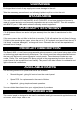
WARNINGS Prolonged short circuit of any supply can cause damage to the unit. Take the necessary precautions in not allowing liquids to spill on or into the unit. STANDARDS This unit conforms to ECD 89/336/EEC & LVD 73/23/EEC. It has been tested and proven to meet all current emission and immunity regulations as set out by the EEC. This unit complies with BS4737 part 1 1988 which relates to security control equipment.
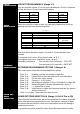
SPECIFICATIONS The following information explains the specifications of the panel. PROCESSOR VERSION SPECIFICATION FOR SOFTWARE REVISION NUMBER V2.0 The software revision number is located on the top of the main processor. SPECIFICATION POWER SUPPLY Power Supply Mains Supply Voltage PSU output voltage Maximum output current Aux. current Battery Fuse Panel Quiescent 230 V AC Nominal 13.7 V Nominal 1 A (total) 500 mA Max.
INSTALLATION Locate the control panel out of sight, such as in a hall, or under stairs or a cupboard, where connection is easy and the detector zone and mains cables can be concealed. Avoid areas subject to high temperature or humidity, such as next to a boiler/heater, in an airing-cupboard, or conservatory. INSTALLATION PROCEDURES When fitting the keypad(s), site them where they are not visible from outside, but where there is adequate light and accessibility for the user.
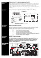
DETECTOR RESET Detector reset (L+ when programmed for ID) INTERNAL DEVICES Internal Sounders, Speakers, Strobe and Keyswitch Wiring Some detectors require the removal of power to reset (such as Viper Plus® or Smoke detectors). You can program the L+ terminal to be used as an ID output using option 7-4. The L+ terminal should then be used as the negative supply for these devices. The positive supply should be taken from the AUX +.
MOUNTING A REMOTE KEYPAD 1 2 3 Choose the keypad location, and then mark holes for mounting. Make sure the cable is run through the backbox. Screw the backbox in the selected position, making sure the cable is not twisted. WIRING A REMOTE KEYPAD Use 6 core cable for connection of all remote keypads. MOUNTING REMOTE KEYPADS WIRING REMOTE KEYPADS Connect the cable into the terminals shown in Diagram C, making sure each wire goes to a like-named terminal in the panel.
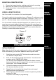
NO PROGRAMMING NEEDED? If no programming is required, close any lids that are open and press the # key. This exits engineering mode. Then refer to the Users Manual for customer options. EXIT ENGINEERING MODE If at any time you want to exit engineering mode, confirm any options you have selected with the * (STAR) key. Then close ALL tamper circuits and wait for approximately 60 seconds after which the panel automatically exits engineering mode. Pressing the # key manually exits engineering.
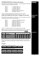
SOUNDER DURATION 3-2 (Range 3-20 minutes) Enter 3-2. The factory default is 15 minutes. You can program a new time by entering one key from the following table. Enter 1 Enter 2 Enter 3 Enter 4 Enter 5 Enter 6 SOUNDER DURATION 3 minutes. LED 1 on. 4 minutes. LED 2 on. 5 minutes. LED 3 on. 10 minutes. LED 4 on. 15 minutes. LED 5 on. (default) 20 minutes. LED 6 on. Press * to confirm the selection. The accept tone then sounds. NIGHT SET/HOME SET EXIT TIME 3-3 (Range 0-90 seconds) Enter 3-3.
CIRCUIT PROGRAMMING CIRCUIT PROGRAMMING 4 (Range 2-7) You can program circuits 2-7 to suit your requirements. Circuit 1 is fixed as a Final exit circuit. Circuit 8 has limited options. ENTER 4-2 4-3 4-4 4-5 ZONE SELECTIONS PROGRAM ZONE 2 3 4 5 ENTER 4-6 4-7 4-8 PROGRAM ZONE 6 7 8 Select the circuit you want to alter. You can then program that circuit by entering one key from the following table. N/S = Night Set Option no.
By pressing the keys 1-8 on the keypad, you can select which zones to be ISOLATED during Home Set. As you press a key, its relevant LED on the display toggles ON or OFF. Any LEDs that are ON are ISOLATED during Home Set, and any that are OFF remain ACTIVE. ENGINEER ACCESS CODE 1-1 The default engineer access code is 7890. To change this code (while in engineering mode), complete the following procedure. 1 Enter 1-1. LEDs 1, 2, 3 and 4 illuminate. 2 Enter the new 4-digit code.
FACTORY DEFAULTS FACTORY PROGRAMMING DEFAULTS 9-9 Restoring Programming Defaults RESTORE DEFAULT Enter 9-9. The sounder gives a rapid pipping sound. Wait for 5 seconds. An PROGRAMMING accept tone sounds, and the factory programming defaults are restored. The user and engineer codes do not change. Note: If any keys are pressed, this procedure is aborted. RESTORE DEFAULT CODES Restoring Code Defaults 1 2 3 4 Place the small link supplied with the spare fuses on the memory link.
ENTRY CIRCUIT Starts the entry timer when activated providing the panel is set. GLOSSARY OF TERMS FIRE (for use with smoke detectors) A zone that when activated emits an ascending sound from any internal speakers. If the panel is set, external sirens and strobes also sound, but in an unset state the external sounders pulse every two seconds. TAMPER A loop that should run through every device on your system. If broken, it triggers the internal speakers.
THIS INFORMATION SHOULD BE KEPT EITHER INSIDE THE CONTROL PANEL OR WITH THE INSTALLER. IT CAN BE USED TO REFER TO PROGRAMMING DETAILS WHEN NEEDED. ZONE ZONE USE / LOCATION 1 2 3 4 5 6 7 8 TIMER FULL NIGHT EXT SOUNDER TICK BOX EXTENDED OPTIONS BATTERY VOLTAGE AUX.
FAULT FINDING A selection of common known problems and solutions are listed below. Problem Programmed 7-5 but zone 1 won’t isolate in night set. Tamper won’t clear with lid on. PA won’t work on the keypad. Mains light not on. Battery not taking over after mains fail. Remote keypad not responding. Zones failing to activate. Zone activates during entry. Zone activates even in day mode. Cause Have not MANUALLY isolated zone when setting panel. Tamper loop open.
Please Note: C & K SYSTEMS is always endeavouring to improve quality and specification of all its products and may alter or amend this product and instructions without notice. C & K Systems Ltd. Unit 24 Walkers Road North Moons Moat Industrial Estate Redditch Worcs. B98 9HE Tel:01527 68111 Fax:01527 68222 Tech Support: Tel: 0345 660533 9am-5pm Weekdays (UK ONLY) C E R TIFIED C O M PA N Y HKQAA Certificate No CC106 Approved email to: info@cksys.co.uk website: cksys.