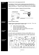
INSTALLATION MANUAL SECURIT 800L+ CONTROL PANEL With additional options
CONTENTS Warnings Standards Warranty Statement Product Description Available Parts Intended use Specifications Processor Version Power Supply Keypads General Factory Defaults Installation Mounting Wiring Battery Detector Circuits L+ as Latch Line L+ as ID- (detector reset) Sounders Strobe Keyswitch Connections Aux DC power PCB Layout Mounting & wiring Keypads Powering Up Entering Engineering Mode Programming Chime Sound options Exit Time Entry Time Sounder Duration Night & Hone Set Exit Time Circuit Program
WARNINGS Prolonged short circuit of any supply can cause damage to the unit. Take the necessary precautions in not allowing liquids to spill on or into the unit. STANDARDS This unit conforms to EMC directive 89/336/EEC & LVD 73/23/EEC. This unit has been tested and has proven to meet all current emission and immunity regulations as set out by the EU. This unit conforms to the requirements of BS4737 part 1 1986 which relates to security control equipment.
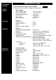
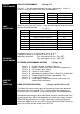
PROCESSOR VERSION SPECIFICATIONS SPECIFICATION FOR SOFTWARE REVISION NUMBER V3.0 The software revision number is located on the top of the main processor POWER SUPPLY Power Supply Mains Supply Voltage PSU output voltage Maximum output current Aux. current Battery Fuse Panel Quiescent 230 V AC Nominal 13.7 V Nominal 1 A (total) 500 mA Max. 1 A (20 mm) 40 mA KEYPADS Keypads Supply Voltage Quiescent Current Active Maximum number allowed 13.
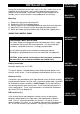
INSTALLATION Locate the control panel out of sight, such as in a hall, under stairs or in a cupboard where connection is easy and the detector zone and mains cables can be concealed. Avoid areas subject to high temperatures or humidity such as next to a boiler, airing cupboard or conservatory. Mounting 1. 2. 3. 4. 5. INSTALLATION PROCEDURES MOUNTING PROCEDURE Remove the lid screws and remove lid. Remove the PCB or keypad packaging. Place the panel in the selected position and mark the three fixing holes.
DETECTOR RESET Detector reset (L+ when programmed for ID) Some detectors require the removal of power to reset (e.g. Viper Plus ® or Smoke detectors). The L+ terminal can be programmed to be used as an 'ID' output using option 7-4. The L+ terminal should then be used as the negative supply for these devices. The positive supply should be taken from the AUX +. SOUNDERS Internal Sounders, Speakers, Strobe and Keyswitch Wiring.
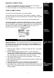
MOUNTING A REMOTE KEYPAD 1. Choose the keypad location and then mark the holes for mounting. 2. Make sure the cable is run through the backbox. 3. Screw the backbox in the selected position making sure it is not twisted. WIRING A REMOTE KEYPAD Use 6 core cable for connection of all remote keypads. MOUNTING REMOTE KEYPADS WIRING REMOTE KEYPADS Connect the cable into the terminals shown below in diagram C making sure each wire goes to a like named terminal in the panel.
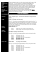
ENTER ENGINEERING MODE To enter engineering mode, enter the engineering code and then press the # (HASH) key. This forces the panel into engineering mode Note: If left unattended for approximately 60 seconds it will revert to day mode.
SOUNDER DURATION (sounder ring time) 3-2 (Range 3-20 minutes) SOUNDER DURATION Enter 3-2. A new time can be programmed by entering a key from the table. Enter 1 Enter 2 Enter 3 Enter 4 Enter 5 Enter 6 3 minutes. Led 1 on. 4 minutes. Led 2 on. 5 minutes. Led 3 on. 10 minutes. Led 4 on. 15 minutes. Led 5 on. (Factory default) 20 minutes. Led 6 on. NIGHT SET / HOME SET EXIT TIME 3-3 (Range 0-90 seconds) NIGHT / HOME SET EXIT TIMER Enter 3-3.
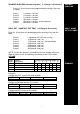
CIRCUIT PROGRAMMING CIRCUIT PROGRAMMING 4 (Range 2-7) Circuits 2 - 7 can be reprogrammed to suit your requirements. Circuit 1 is fixed as a Final exit circuit. Circuit 8 has limited options. ENTER 4-2 4-3 4-4 4-5 ZONE SELECTIONS PROGRAM ZONE 2 3 4 5 ENTER 4-6 4-7 4-8 PROGRAM ZONE 6 7 8 Select the circuit you wish to alter, it may then be programmed by entering one key from the following table. N/S = Night Set Option no.
ENGINEER ACCESS CODE 1-1 ENGINEER ACCESS CODE The engineer access code is programmed to 7890 by default. To change this code (while in engineering mode): 1. Enter 1-1. LEDs 1, 2, 3 and 4 will illuminate. 2. Enter the new 4 digit code. After each keypress one LED will go out. The speaker will emit an accept tone if the new code is accepted. If the speaker emits an error tone, then your new chosen code is invalid. This could be due to a conflict with another code.
FACTORY DEFAULTS FACTORY PROGRAMMING DEFAULTS 9 -9 Restoring programming Defaults. RESTORE DEFAULT PROGRAMMING RESTORE DEFAULT CODES Enter 9-9, The sounder will give a rapid pipping sound, wait for 5 seconds, an accept tone sounds, the factory programming defaults are restored. The user and engineer codes do not change. Note: If any keys are pressed this procedure will be aborted. Restoring Code Defaults 1. Place the small link supplied with the spare fuses, on the memory link.
ENTRY CIRCUIT This will start the entry timer when activated providing the panel is set. FIRE (for use with smoke detectors etc.) A zone that when activated emits an ascending sound from any internal speakers. If the panel is set, external sirens and strobes will also sound but in an unset state the external sounders will pulse every two seconds. TAMPER This is a loop that should run through every device on your system. If broken, it triggers the internal speakers.
THIS INFORMATION SHOULD BE KEPT EITHER INSIDE THE CONTROL PANEL OR WITH THE INSTALLER. IT CAN BE USED TO REFER TO PROGRAMMING DETAILS WHEN NEEDED. ZONE 1 2 3 4 5 6 7 8 TIMER FULL NIGHT EXT SOUNDER TICK BOX 1 EXTENDED OPTIONS BATTERY VOLTAGE AUX.
FAULT FINDING A selection of common known problems and solutions are listed below. Problem Cause Answer Programmed 7-5 but zone 1 will not isolate in night set. Zone 1 is permanently lit Have not MANUALLY isolated zone when setting panel. When night setting enter code * 0 * 1. Memory default link is on. PA will not work on the keypad Mains light not on.
Wiring Diagram Please Note: IntelliSense are always endeavouring to improve quality and specification of all its products and may alter or amend this product and instructions without notice. All information is given in good faith but without warranty. Certificate No CC106 IntelliSense UK Unit 25 Walkers Road, North Moons Moat Industrial Estate, Redditch, Worcestershire.