
Installation manual

SYSTEM 238 Installation Manual
20
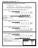
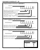
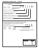
KEYPAD LABEL DRAWER
Each keypad comes with a Label Drawer and quick reference
operating label. Follow the diagram below to set up the Label Drawer
Example of drawer pulled
from the left
Example of drawer pulled
from the right
Regular maintenance and inspection (at least monthly) by the installer
and frequent testing by the user are vital to the continuous and
satisfying operation of any alarm system. The installer should assume
the responsibility for developing and offering a regular maintenance
program to the user, as well as acquainting the user with the proper
operation and limitations of the alarm system and its component parts.
Recommendations must include a specific program of regular
testing (at least weekly) to insure that the system is operating
properly at all times.
TELEPHONE LINE PROBLEMS
In the event of telephone line problems, disconnect the SYSTEM 238
by removing the modular connector plug from the Telco interface jack.
Do not disconnect the connection inside the SYSTEM 238
cabinet. Doing so will prevent the premise phones from operating. If
your phone works correctly after the control panel has been discon-
nected from the phone line, the control panel has a problem and should
be returned for repair.
If the phone does not work after you have disconnected the control
panel from the phone line, notify the telephone company and request
prompt repair. The user may not under any circumstance (in or
out of warranty) attempt any service or repairs on the SYSTEM 238.
The control panel must be returned to C&K SYSTEMS or an authorized
service agency for repairs.
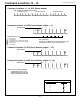
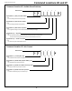
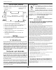
DS1
WATCH
DOG
Watchdog Indicator
The SYSTEM 238 is protected by an advanced
circuit, called a Watch Dog circuit, that constantly
monitors the microprocessor.
As long as the panel has power and is operating
normally, the Watch Dog LED (DS1) on the circuit
board will flash. If the Watchdog circuit detects a failure, it will attempt
to reset the panel.
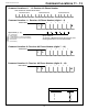
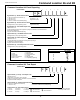
KEYPAD PLASTIC BASE
Rotate keypad base so
drawer slot faces the correct direction
Plastic
drawer
Plastic drawer and label slide into
drawer on back of keypad base
Plastic drawer
TESTING
Once the installation is complete, connect AC and DC power. Com-
plete programming, if required. Test all panel operations.
TO THE INSTALLER
If the panel does not operate properly, and the Watchdog LED no
longer flashes, call the C&K Technical Support Hotline at 1-800-
227-8065 in the U.S. or your local C&K Representative.
FCC NOTICE
WARNING: This device is intended to be installed by a profes-
sional alarm installer.
The user shall be cautioned that changes or modifications
not expressly approved by C&K SYSTEMS could void the
user's authority to operate the equipment.
This equipment complies with FCC Rules, Part 68.
On the outside of this equipment is a label that contains, among other information, the FCC
Registration Number and Ringer Equivalence Number (REN) for this equipment. If re-
quested, provide this information to your telephone company.
The REN is useful to determine the quantity of devices you may connect to your telephone
line and still have all of those devices ring when your number is called. In most, but not all
areas, the sum of the RENs devices should not exceed five (5.0). To be certain of the
number of devices you may connect to your line, as determined by the REN, you should
call your local telephone company to determine the maximum REN for your calling area.
Should you experience trouble with the telephone lines, disconnect the equipment from
the line to determine the source of the trouble. If it is determined that the equipment is
malfunctioning, discontinue its use until the malfunction has been corrected. Any repairs
or alterations made by the user to this equipment, or equipment malfunctions, may give the
telephone company cause to request the user to disconnect the equipment. Repairs to this
equipment should be made by an authorized agent of C&K Systems, Inc. Contact your
local alarm installation company for service.
Should this equipment cause harm to the telephone network, the telephone company may
temporarily discontinue your service. If possible, they will provide you with advance no-
tice. Otherwise they will notify you as soon as possible. The telephone company will also
advise you of changes in its facilities, equipment, operations or procedures which could
affect the operation of your equipment, allowing you the opportunity to maintain uninter-
rupted service. You will also be advised of your right to file a complaint with the FCC.
This equipment must not be used on party lines or coin operated phone lines.
FCC Part 15 Notice
This equipment has been tested and found to comply with the limits for Class B digital
devices, pursuant to Part 15 of the FCC Rules. These limits are designed to provide reason-
able protection against harmful interference in a residential installation.
This equipment generates, uses, and can radiate radio frequency energy, and if not in-
stalled and used in accordance with the instructions, may cause harmful interference to
radio communications. However, there is no guarantee that interference will not occur in
a particular installation.
If this equipment does cause harmful interference to radio or television reception, which
can be determined by turning the equipment off and on, the user is encouraged to try to
correct the interference by one or more of the following measures:
Reorient the radio/television antenna;
Connect the AC transformer to a different outlet so that the equipment and radio/tele-
vision are on different branch circuits;
Relocate the equipment with respect to the radio/television;
Consult the dealer or an experienced radio/television technician for help.
FCC Registration Number: C2DCHN-18741-AL-E
Ringer Equivalence: 0.3B
CANADIAN EMISSION REQUIREMENTS
This Class B digital apparatus meets all requirements of the Canadian Interference-
Causing Equipment Regulations.
Cet appareil numérique de la classe B respecte toute les exigences du Règlement sur
le matériel brouilleur du Canada.
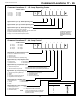
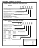
1. Fill in the zone descriptions inside the label.
2. Mark "Y" or "N" to indicate if zones can be bypassed or not.
3. Determine if the drawer will slide from the right or left.
4. Peel the cover off the drawer glue.
5. Align the edge of the label with the edge of the drawer. Center
the label top to bottom.
6. Press the label onto the glue. Avoid trapping air
bubbles under the label.
7. Slide the drawer/label into the slot on the back of the
keypadbase.