
Datasheet
K–13
Dimensions are shown: Inch (mm)
Specifications and dimensions subject to change
www.ck-components.com
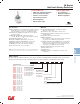
K
Rotary
Models A
vailable
M Series
Half-inch Rotary Switches
Features/Benefits
•
Multi-pole and multi-positions
•
Panel and PCB mounting
•
Stainless steel actuator
•
Non-shorting contacts
•
RoHS Compliant
•
IP67 (F option only)
Typical Applications
•
Test equipment
•
Industrial equipment
•
Medical equipment
Specifications
CONTACT RATING: Q contact material: Carry-6 AMPS continuous.
Switch-250 mA max. @ 125 V AC or 28 DC. Non-shorting
contacts standard. See page K-16 for additional ratings.
ELECTRICAL LIFE: 10,000 make-and-break cycles at 150 mA,
125 V AC or 28 DC.
CONTACT RESISTANCE: Below 20 mΩ typ. initial @
2-4 V DC, 100 mA, for both silver and gold plated contacts.
INSULATION RESISTANCE: 10
10
Ω min.
DIELECTRIC STRENGTH: 600 Vrms min. @ sea level.
OPERATING & STORAGE TEMPERATURE: –30ºC to 85ºC.
OPERATING TORQUE: 4-7 ounces-inches typ. initial.
SOLDERABILITY: Per MIL-STD-202F method 208D, or
EIA RS-186E method 9 (1 hour steam aging).
NOTE: Specifications and materials listed above are for switches with standard options.
For information on specific and custom switches, consult Customer Service Center.
Materials
HOUSING AND BUSHING: Zinc alloy, bright zinc plated,
with clear chromate finish.
ACTUATOR: Zinc alloy, nickel plated or stainless steel.
BASE: Diallylphthalate (DAP) or melamine phenolic, with insert
molded terminals.
ROTOR: Glass filled polyester (UL 94V-0).
MOVABLE CONTACTS:
Non-shorting: Q contact material: Copper alloy, silver plated.
See page K-16 for additional contact materials.
STATIONARY CONTACT & ALL TERMINALS: Q contact material:
Copper alloy, silver plated. All terminals insert molded. All
terminals present regardless of number of switch positions.
See page K-16 for additional contact materials.
CONTACT SPRING: Music wire, phosphate coated.
STOP PIN: Stainless steel.
STOP RING: Brass.
HARDWARE: Nut: Brass, nickel plated; Lockwasher: Steel,
nickel plated.
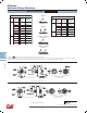
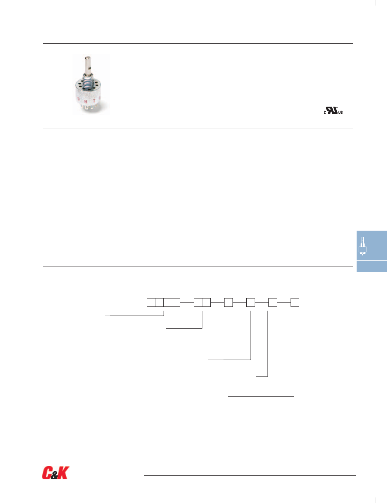
Build-A-Switch
To order, simply select desired option from each category and place in the appropriate box. Available options are shown and
described on pages K-14 thru K-18. For additional options not shown in catalog, consult Customer Service Center.
Switch Function
MA00
SP
, 10 pos., 36°
MA02 SP, 2 pos., 36°
MA03 SP, 3 pos., 36°
MA04 SP, 4 pos., 36°
MA05 SP, 5 pos., 36°
MA06 SP
,
6 pos.,
36
°
MA10 SP, 10 pos., 36°
MB00 DP, 5 pos., 36°
MB03 DP
,
3 pos.,
36
°
MB04 DP, 4 pos., 36°
MB05 DP, 5 pos., 36°
MC00 SP
,
12 pos., 30°
MC03 SP, 3 pos., 30°
MC07 SP, 7 pos., 30°
MC12 SP, 12 pos., 30°
MD00 DP
,
6 pos., 30°
MD06 DP, 6 pos., 30°
ME00 SP, 10 pos., 36°
ME04 SP, 4 pos., 36°
MF00 DP, 5 pos., 36°
MG00 SP
,
12 pos.,
30
°
MH00 DP, 6 pos., 30°
Contact Material
Q
Silver
G Gold over silver
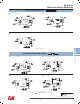
Actuator & Bushing
L1
.650" long, flatted
L2 Screwdriver slot, flush
L3 .650" long,
round
S1 .650" long, flatted
S2 Screwdriver slot,
flush
S3 .650" long, round
S6 .785" long,
slot
Short/Non-short
N
Non-shorting contacts
Terminations
Z
Solder lug
C PC
Thru-hole
Seal
D
No seal
F Splashproof shaft & panel seal (IP67)