Spirit DataCine Filmscanner SDC 2002 Operating Instructions Software Version 4.
Published by THOMSON Broadcast & Media Solutions GmbH Brunnenweg 9 D-64331 Weiterstadt, Germany P.O. Box 1165 Tel: +49 (0) 6150-104-0 Fax: +49 (0) 6150-104-300 Web Site www.thomsongrassvalley.com Trademarks All product names mentioned in this manual are the trademarks of their respective owners. Copyrights Information in this document is subject to change without notice.
SDC 2002 Contents CONTENTS 1. About the Manual 1.1. 2. 3. Software state . . . . . . . . . . . . . . . . . . . . . . . . . . . . . . . . . . . . . . . . . . . . . . . . . . . . . . . . 1-1 Control and display elements 2.1. Film Scanner . . . . . . . . . . . . . . . . . . . . . . . . . . . . . . . . . . . . . . . . . . . . . . . . . . . . . . . . . 2-1 2.2. 2.2.1. 2.2.2. Control panels . . . . . . . . . . . . . . . . . . . . . . . . . . . . . . . . . . . . . . . . . . . . . . . . . . . . . . .
Contents SDC 2002 3.9.4. Adjust horizontal and vertical blanking . . . . . . . . . . . . . . . . . . . . . . . . . . . . . . . . . . . . 3-35 3.10. 3.10.1. 3.10.2. 3.10.3. 3.10.4. 3.10.5. 3.10.6. 3.10.7. 3.10.8. 3.10.9. Matching to different color and monochrome film types . . . . . . . . . . . . . . . . . 3-37 Define film type . . . . . . . . . . . . . . . . . . . . . . . . . . . . . . . . . . . . . . . . . . . . . . . . . . . . . . . . 3-37 Adjust film masking . . . . . . . . . . . . . . . . . . . .
SDC 2002 6. Contents Maintenance 6.1. Safety instructions . . . . . . . . . . . . . . . . . . . . . . . . . . . . . . . . . . . . . . . . . . . . . . . . . . . 6-2 6.2. 6.2.1. 6.2.2. 6.2.3. Clean the film drive mechanism . . . . . . . . . . . . . . . . . . . . . . . . . . . . . . . . . . . . . . . 6-3 Clean illumination slit and film guiding of the film gate . . . . . . . . . . . . . . . . . . . . . . 6-4 Clean the capstan roller . . . . . . . . . . . . . . . . . . . . . . . . . . . . . . . . . . . .
Contents IV SDC 2002 Operating Instructions - Rev. 1 / 6.
1. General SDC 2002 1. ABOUT THE MANUAL This manual is part 1 of the Customer’s Manual. It informs the user about control and display elements, operational preparations, operation, maintenance and trouble shooting. 1.1. SOFTWARE STATE 1.1.1. SDC 2002 DataCine The present manual documents the following software states: Film scanner SDC 2002 operating software version V4.60 GCP: Graphical Control Panel 1.1.2. Op. sw V1.8.
1. General 1-2 SDC 2002 Operating Instructions - Rev. 1 / 6.
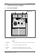
2. Control and Display Elements SDC 2002 2. CONTROL AND DISPLAY ELEMENTS 2.1. SDC 2002 FILM SCANNER 1 1 SDC 2002 2 Power on / off Thomson 11 3 2 4 5 Spirit DataCine Fig. 201: SDC 2002 Spirit DataCine film scanner Overview 1 Lamps (2x) ... serve the lighting of the film scanner interior. Can be switched off, if required. 2 Power ... mains switch for switching on/off the film scanner. 3 Locking lever ... locking lever for the optical block (LGA, lens gate assembly).
2. Control and Display Elements 4 Wind A / B SDC 2002 ... switch for selecting the winding direction of the threaded film. WIND A Winding direction in ccw direction. WIND B Winding direction in cw direction. Application: for rewinding a film threaded with inverse sides. 5 2-2 Control Panel ... Local Control Panel FH 6500 for Play, Stop, Step, Shuttle, FPN, Framing, Stand by, additional functions and remote delegation. For further details see section 2.2.1. Operating Instructions - Rev. 1 / 6.
2. Control and Display Elements SDC 2002 2.2. CONTROL PANELS 2.2.1. LOCAL CONTROL PANEL FH 6500 1 Remote F1 F2 F3 F4 F5 F6 2 3 Stand by FPN FPN FRM FRM S8 S16 4 5, 6 7 Shuttle 8 Step Step 9 Play Play 10 Stop 11 Fig. 202: Local Control Panel FH 6500 1 Key Remote ... pressing the key delegates the control functions from the Local Control Panel to an external Remote Control Panel and vice versa (toggle mode). The key is lit when the control functions are remotable.
2. Control and Display Elements SDC 2002 2 Function keys (6x) ... not assigned. Quick selection for future functions. 3 Key Stand by ... Indicates that the machine is ready for operation. Momentary-contact pushbutton switch for switching on the standby mode. The winding motors are switched on (film is automatically tightened) and the capstan motor is released for operation. Prior to settings, always carry out FPN correction first. During operation, the Stand by key lamp has to be lit all the time.
2. Control and Display Elements SDC 2002 9 Keys Step / ... single-frame selection forward/reverse. On pressing the step key, the film scanner will automatically enter the Stop mode. Still frame has broadcast quality. After Stop the projection lamp is switched to reduced lighting power immediately (approx. 5 s after Stop the safety shutter is closed). 10 Keys Play / ... film presentation in the forward or reverse mode. Can be entered from all operating modes.
2. Control and Display Elements 2.2.2. SDC 2002 GRAPHICAL CONTROL PANEL GCP 1 GCP Eventlist Dialog buttons Power Trackball delegation: For future use to panel to machine TK button TK Previous Control Prev Ctrl Trackball Lock Acceleration Help Digits Unity Dialog function buttons 2. Display Digipots Machine controls Fig. 203: Functional Control Panel CP1 Machine Control Section The Machine Control Section is located in the lower right corner of the GCP.
2. Control and Display Elements SDC 2002 TK 4 3 2 1 JOG VAR STL 5 Step Step 6 Play Stop Play Fig.
2. Control and Display Elements SDC 2002 TK Button To control the telecine press the TK BUTTON (Button gets lit). All transport controls are now delegated to the DataCine. Display Button Below the trackball on the left you find the DISPLAY BUTTON. Pressing this button delegates the trackball to the GUI (graphical user interface). Machine Deck Button Below the trackball on the right you find the MACHINE DECK BUTTON.
3. Operational Preparations SDC 2002 3. OPERATIONAL PREPARATIONS The sections of the chapter ”Operational Preparations” have a defined order. Preceding sections are mostly precondition for the succeeding sections (such as ”Perform FPN correction” before ”Thread the film” etc.) and should therefore be considered when setting into operation. 3.1. HARDWARE CONDITIONS GCP Installation The Graphical Control Panel has to be connected to the Spirit DataCine.
3. Operational Preparations 3.2. SDC 2002 POWER-UP The film scanner is powered up with the mains switch ”Power” at the front of the film scanner (Fig. 301: 1). To switch on the Graphical Control Panel GCP1 ( Fig. 301: 2), press the power button 3. To avoid EMC (electromagnetic compatibility) problems keep the rear doors always closed during operation! After 15 minutes operating time, all characteristics are stabilized.
3. Operational Preparations SDC 2002 3.3. BASIC ADJUSTMENTS OF THE FILM SCANNER 3.3.1. CONFIGURATION OF THE CONTROL PANEL & DELEGATION OF OPERATIONAL CONTROL Configuration of the graphical control panel is mostly performed only once. For details, see Customer’s Manual GCP. After “power on” the display of the graphical control panel shows the power-up test, and subsequently the HOME menu. Fig. 302: Home Menu Ctrl Press once the CONTROL BUTTON to get control over the Spirit DataCine.
3. Operational Preparations 3.3.2. SDC 2002 SELECT TV STANDARD If the momentary TV standard does not correspond to the desired standard, change the TV standard as follows. Select the main menu ”TK Config”, SDTV or HDTV submenu. Fig. 303: :TK config menu, submenu SDTV Window SDTV / HDTV serves to choose the TV standard. The change of the TV standard is acknowledged by a beep tone. Only those outputs are active, which are selected by the TV standard.
3. Operational Preparations SDC 2002 Note! When switching over the TV standard, the film drive has to be in the stop mode. Subsequently, a restart of the film scanner is made with corresponding message on the display of the control panel GCP1. TV standard Fig. 304: : Home menu with the new TV standard Operating Instructions - Rev. 1 / 6.
3. Operational Preparations SDC 2002 3.4. USER-SPECIFIC CONFIGURATION OF THE FILM SCANNER 3.4.1. CHANGE OPTICAL BLOCK Changing the optical block (Super 16 mm, Super 35 mm/FA 35mm LGA - Lens Gate Assembly) optically matches the film scanner to the wanted film format. Change LGA 1. Remove the threaded film from the optical block, if necessary. 2. Unlock the optical block (LGA, lens gate assembly). For this purpose, move the locking lever on the right of the optical block in upwards ccw direction.
3. Operational Preparations SDC 2002 3.4.2. CHANGE THE FILM GATE Super optical blocks need an additional film gate (option) when operating standard films. Change 1. Open the film gate locking. For that reason hold the film gate locking lever at the lower end and pull it up. 2. Remove the built-in film gate. 3. Insert and lock the new film gate. 4. Perform FPN correction (see section 3.5.). Film gate Film gate locking lever Fig.
3. Operational Preparations 3.4.3. SDC 2002 USING EFFECT FILTERS Precautions! D Insert a filter drawer into the filter drawer slot with filter facing up and the filter side heading as shown in the figure below. D Take care of not fastened filters or hold downs. These can drop into the AIH or LGA and may cause damage to the system. D Do not insert any foreign object into the filter drawer slot. This could result in a malfunction and a damage to the unit.
3. Operational Preparations SDC 2002 AIH Attention! Never insert the filter with the filter facing down! Slot Fig. 308: Note! The filter drawer is correctly installed when the white filter drawer indicator is visible! To ensure the correct position of the filter and electromagnetic compatibility, the filter door must always be installed during operation. AIH Filter Door Filter drawer indicator LGA Fig. 309: Operating Instructions - Rev. 1 / 6.
3. Operational Preparations SDC 2002 1. General The Effect Filter Case FH 6910 facilitates the usage of optical effect filters for the Spirit DataCine film scanner. It consists of a selection of drawers, which position filters in the optical path between the projection lens and the CCD sensors. 14 different kinds of supermist filters are provided with the upgrade kit. Each filter is protected in its own drawer.
3. Operational Preparations SDC 2002 Filter types The type of the filter White Supermist or Black Supermist can be identified at the front label of the drawer. Fig. 311: 2. Additional Filter and Filter Drawer Set a. Filter Drawer Set (5 pcs, w.o. filters) is optional available. Spare part order no.: 3 119 100 288 b. Filters Please order spare or additional filters directly from: South London Filter LTD.
3. Operational Preparations SDC 2002 3. Mounting Filter & Filter Drawer Preparation of customer-prepared Filter Prepare filter material according to the following measurements: Filter size: Area 63.5mm x 63.5mm [2.5 in x 2.5 in] with sloped edges Maximum thickness used with filter hold-down 0.65 mm [0.025 in] used without filter holder 2.0 mm [0.08 in] 63.5 mm [2.5 in] 63.5 mm [2.5 in] 30o TYP. 2o 19.05 mm [0.750 in] Fig.
3. Operational Preparations SDC 2002 4. Insert Filter into Filter Drawer Fixing Filter only with Filter hold-down (for test purposes only) Insert a prepared filter into the filter drawer and fix it at the drawer with the filter holddown as shown in figure Fig. 314: . Do not remove the tape protection foils from the filter drawer and filter hold-down. Note! The height of filter and filter hold-down must not surmount the filter drawer upper edge.
3. Operational Preparations SDC 2002 6. Fixing Filter with double-sided Tape The filter drawers are provided with a double-sided adhesive tape. This tape serves for fixing a filter permanently in the drawer. Insert a prepared filter into the filter drawer and fix it with the double-sided tape as shown in Fig. 316: . Before doing this, remove the protective foil from the doublesided tape in the drawer. Important! The thickness of filter material must not surmount the filter drawer upper edge.
3. Operational Preparations SDC 2002 7. Insert Filter Drawer Adjust Focus to the value >15,000 Menu Home - focus Filter drawer cannot be inserted if the focus slide is in the range of 0 up to 15,000. s Fig. 317: Remove the filter door from the AIH, for this purpose loosen the captive fastener, see Figure Fig. 318: . Insert the filter drawer into the filter drawer slot with filter facing up and the filter side heading as shown in the figure below.
3. Operational Preparations SDC 2002 Re-install filter door. To avoid damage to the focus mechanism and filter drawer and to ensure electromagnetic compatibility, press the filter door firm against the sealing tape (around the compartment opening) and tighten it with the captive fastener. Warning! To ensure the correct position of the filter and electromagnetic compatibility, the filter door must always be installed during operation.
3. Operational Preparations SDC 2002 Normal FPN correction should always be done without the effect filter to ensure perfect correction. If FPN is performed with a filter inserted, FPN correction will only be correct for this special filter. 8. Adjust Focus The usage of light effect filters can cause de-focussing of the system. It is recommended to adjust the focus of the AIH when an effect filter is being installed or changed. Setting The focus slider controls the focus servo in the film scanner.
3. Operational Preparations SDC 2002 9. Trouble Shooting Remove Parts dropped in In case of parts have been dropped in to the inside of the AIH system, take them out as follows (Figure Fig. 321: Remove the Lensgate Assembly (LGA) and take out the parts which have dropped in. if necessary Remove the cover of the AIH system and take out parts which have dropped in.
3. Operational Preparations SDC 2002 Blocked up Filter In case a filter is blocked up in its compartment and the “remote focus slide” is locked, release the focus slide by means of the GCP menu “Diagnosis” Focus Release” button. Fig. 322: Monitoring menu with submenu Diagnosis - Release Focus button Operating Instructions - Rev. 1 / 6.
3. Operational Preparations 3.4.4. SDC 2002 SETUP FILM DECK Set filmdeck settings in th main menu “TK Config” Fig. 323: Menu TK Config Set Core diameter Auto Stop Max Shuttle Speed 35mm Max Shuttle Speed 16mm in main menu ”SETUP”. Configuration possibilities concerning film deck are to be found in the GCP Manual. 3.4.5. SETUP FILM Open the main menu Film and adapt the film scanner to the film to be played. Use the button “Filmtype” Fig.
3. Operational Preparations SDC 2002 3.4.6. SELECT TV RATIO 4:3 / 16:9 Open then main menu TK Config, select submenu SDTV Fig. 325: Press button “SDTV Ratio” and select 4:3 or 16:9. 3.4.7. SELECT SPEED Open then main menu TK Config Fig. 326: Select or adjust a fixed (or a variable) film speed for the film scanner. Selection of the film speeds and explanations, see GCP manual. Operating Instructions - Rev. 1 / 6.
3. Operational Preparations 3.5. SDC 2002 PERFORM FPN CORRECTION Remote F1 F2 F3 F4 F5 F6 Stand by FPN correction: Press both FPN keys together FPN FPN FRM FRM Shuttle Step Step Play Play Stop Fig. 327: Local control panel of the film scanner Performing a FPN (Fixed Pattern Noise) correction effects an automatic noise signal compensation in the white as well as an automatic white balance adjustment.
3. Operational Preparations SDC 2002 FPN conditions: 1. Perform FPN the first time after a “warm up” of about 15 minutes. 2. Perform FPN before threading the film (FPN correction with film: picture adjustment useless and thermal film damage possible). 3. Repeat FPN, if the environment temperature changes by more than 5°C. 4. Repeat FPN to compensate illumination level losses, if the environment temperature changes by more than 2°C. With super 16mm optical block: 1.
3. Operational Preparations 3.6. SDC 2002 THREAD THE FILM Thread the film according to the film threading path printed on the film deck. Before the film can be threaded, the following preparations have to be made. 3.6.1. DEFINE WINDING DIRECTION The both switches A/B on the film deck are to be set in position A (= PLAY position) for normal film operation. During operation both film reels wind anti-clockwise. Position B is used only for rewinding a film wound side-inverted.
3. Operational Preparations SDC 2002 3.6.2. USING FIXED WINDING PLATES Two fixed winding plates can be mounted on the filmscanner.To adapt any filmtypes to the winding plates use the inlays for bobbins or the inlays for reels as well as the two locking devices. The inlays for 16/35mm films are delivered with the filmscanner or can be ordered separately (9mm spindle= FH6609 / 8mm spindle FH6608). The inlays for S8mm films are optional. 3.6.3. MOUNT FILM ROLLS Mounting film rolls 1.
3. Operational Preparations Attention! 3.6.4. SDC 2002 When operating with bobbins, the inner shaft of the locking device has to protrude, otherwise press the locking button and the shaft will jump out. MOUNT FILM REELS If the film to be played is a film reel, the full film reel has to be mounted on the leftsided reel spindle and the empty film reel on the right-sided one. Winding plates Inlays for film reels Fig. 331: Fixed winding plates with bobbin inlays 1.
3. Operational Preparations SDC 2002 2. Mount the reel inlay to the fixed winding plate (on each side) 3. Slide the film reel on the reel spindle. 4. Plug in the film reel onto the carrier of the reel spindle. 5. Slide the locking device on the reel spindle until it locks in with an audible click. Attention: When operating with film reels, the inner shaft of the locking device has to be sunk, otherwise press the locking button and slide the inner shaft backwards.
3. Operational Preparations 3.6.6. 3.6.6.1. SDC 2002 THREAD FILM CORRECTLY FILM THREAD DIRECTION S8 mm film (option S8 scanning req.) Put perforation to the film deck plate 16mm film Put perforation to the film deck plate 35mm film Put audio track to the film deck plate Film roll with bobbin o p e r a t i o n Slide the full film roll, as shown below, onto the left winding plate and lead the film on film path ”A” (printed on the film deck plate) to the right winding plate.
3. Operational Preparations SDC 2002 3.7. ADJUST FRAME LINE To achieve a correct vertical picture position for 35mm films press “Framing” key on the Local Control Panel several times. This effects a coarse correction of the frame bar downward (1 perforation hole downward per film picture). Shift frame line until it disappears under the upper or lower picture border. or via Grahpical Control Panel GCP: Select the Home menu. Fig.
3. Operational Preparations 3.8. SDC 2002 ADJUST FOCUS Graphical Control Panel GCP1 The focus slider controls the focus servo in the film scanner. Focussing can be done either with the digipot control or by sliding on the touchscreen. Setting Hitting the AID button sets zoom and contour to maximum and slows down the film speed to 6 fps. Thus, film grain will appear as large and clear as possible which helps to find the optimum focus position. Fig.
3. Operational Preparations SDC 2002 3.9. ADJUST SIZING FORMAT The sizing format (scanning and reproduction format) of the film scanner is set in the sizing menu. Preconditions 3.9.1. 1. The TV standard is selected (i.e., line standard is determined, see section 3.3.2.). 2. According to film format (16mm, S16mm, 35mm, S35mm), the suitable optical block is used (see section 3.4.1.). 3. The film is threaded correctly (see section 3.6.). 4. The frame line is adjusted (see section 3.7.).
3. Operational Preparations 2 Select submenu “Repro” SDC 2002 Touch screen Select a fixed scan format by pressing “Fixed Aspect” and according to the specification of the film scanning format on the film box. 1207 x 1079 959 x 549 21.25 19.00 18.75 Fig. 338: Sizing menu, submenu Repro 3-32 Operating Instructions - Rev. 1 / 6.
3. Operational Preparations SDC 2002 3.9.2. SELECT FIXED REPRODUCTION FORMAT (FIXED REPRO) When selecting a fixed film scanning format (see section 3.9.1.), a suitable reproduction format is selected each time automatically for this film. If an other reproduction format should be wanted nevertheless, proceed as follows. Selection 3 4 Where? Function Press the button Sizing Control panel The Sizing menu appears.
3. Operational Preparations 3.9.3. SDC 2002 ADJUST SIZING FORMAT VARIABLY If the fixed reproduction format (as selected in section 3.9.2. ) does not yet correspond to the requests, the reproduction format can also be adjusted variably. Selection Where? Function 6 Press button Sizing Control panel The Sizing menu appears. 7 Select Size Window Touch screen Sets sizing adjustments to default values. 1080 60 I 24500 x 19000 12250 / 9307 21110 x 19000 18750 / 9306 21102 x 19000 18750 / 9500 Fig.
3. Operational Preparations SDC 2002 3.9.4. ADJUST HORIZONTAL AND VERTICAL BLANKING Selection Where? Function 9 Press button Sizing Control panel The Sizing menu appears. 10 Select submenu Blanking Sizing menu Submenu ”Blanking” appears. 1201 x 1151 959 x 575 Fig. 341: Submenu ”Blanking” 11 Select the Film button Submenu Blanking The Film blanking adjustments (Size and Position) determine the section of the picture which is written into the frame store.
3. Operational Preparations SDC 2002 The TV blanking adjustments (Size and Position) determine the section of the picture which is read out of the frame store. TV blanking is not part of the picture. It behaves like an external blanking rendered by a production switcher. 12 Select the TV button Submenu Blanking Adjust with the digipot or sliders the vertical blanking, and the horizontal blanking. The blanking settings should limit film picture content only slightly.
3. Operational Preparations SDC 2002 3.10. MATCHING TO DIFFERENT COLOR AND MONOCHROME FILM TYPES Precondition for this section are the preceding sections of chapter 3. The most important ones are: 3.10.1. 1. Film scanner user-specifically configurated 2. FPN correction performed 3. Film threaded 4. Frame line optimized 5. Picture optically focused 6. Sizing format adjusted DEFINE FILM TYPE Select 1 Press button Film Where? Adjust function Control panel The Film menu appears Fig.
3. Operational Preparations 2 3 Double click function button ”unity ALL” Select button Film Type SDC 2002 left to the touchscreen Adjusts standard values for the complete film menu. Film menu Make your choice from the drop - down menu. For each filter type, positive and negative setting are available. This function also switches the gamma according to the selected film type. Fig.
3. Operational Preparations SDC 2002 3.10.2. ADJUST FILM MASKING Select 5 For matching to special films, select submenu “Masking”, Where? Adjust function Film Menu Opens submenu ”Film masking” comm_1 comm_1 comm_2 comm_3 1.000 0. 0.000 1. 0.000 0. comm_4 comm_5 comm_6 comm_7 0.000 0.000 1.000 comm_8 TCP5285 TCPLIMX spec_1 Fig. 344: Submenu ”Film masking with pull - down menu matrix 6 Click button Matrix. Select fixed, preadjusted matrix coefficients from the drop-down menu.
3. Operational Preparations 7 SDC 2002 If the correct color reproduction in the output pictures not yet achieved, click on new matrix in the drop - down menu An additional window “Enter new Matrix” opens and a two lined keypad is activated in the top of the menu. Fig. 346: Set new matrix name 8 Type in the name for the new matrix coefficient Submenu Masking Confirm by pressing the OK button. Now the coefficients in the matrix window can be modified.
3. Operational Preparations SDC 2002 3.10.3. ADJUST INTENSITY OF FILM ILLUMINATION Select 10 Press menu button Film Where? Adjust function Control panel The Film menu appears 85% Slide CCD Output for 100 % video level 100 % Flash button 100 % 100 % Fig. 348: Film menu For test purposes use testpoint 1 AIH / A/D Menu Monitoring Fig. 349:Menu Monitoring, submenu Test Pnt 11 Shift slider “Light” or use the trackball Operating Instructions - Rev. 1 / 6.
3. Operational Preparations 12 Run film for adjusting the intensity of film illumination SDC 2002 Search for a scene with low film density (bright lights, clouds or similar) and adjust the intensity of film illumination in such a way that the brightest one of the RGB video signals reaches a level of 100 % (oscilloscope). ”CCD Output Level Display: During adjustment watch the CCD Output Level Display! Make sure that this level is around 85%.
3. Operational Preparations SDC 2002 3.10.4. ADJUST ANALOG SIGNAL BASIC GAIN Select 14 Press button Gain Where? Adjust function Film Menu Opens pull down menu and shows the possible selections for analog basic gain. 100 % 100 % 100 % Fig. 350: Film menu with pull down menu Gain 15 Run film for judging the film density 16 Select 6dB With very dense film material, use basic gain ”6 dB”. Pulldown menu Selection ”6 dB” doubles now the analog gain.
3. Operational Preparations 3.10.5. ADJUST LIFT & GAIN (BLACK & WHITE SIGNAL LEVEL RANGE) Select 17 SDC 2002 Press menu button Film Where? Adjust function Control panel The Film menu appears 100 % 100 % 100 % Fig. 352: Film menu For test purposes use testpoint 3 Gain / Lift Menu Monitoring Fig. 353:Menu Monitoring, submenu Test Pnt 18 3-44 Run film scanner for adjusting the white level (and then the black level) Search for a scene with picture white (or picture black) and stop.
3. Operational Preparations SDC 2002 19 Matching Gain for the white level adjustment & Matching Lift for the black level adjustment Film menu Adjust picture white in the R, G and B channels with the corresponding digipot controls or by sliding on the touch screen matching Gain in all channels to 100 % video signal. Adjust picture black in the R, G and B channels in matching lift RGB to 1 % setup) This is the basic adjustment for the film to be played. 20 Re-wind film Operating Instructions - Rev.
3. Operational Preparations 3.10.6. ADJUST BLACK LEVEL (BLACK MASTER & BLACK RGB*) Select 21 SDC 2002 Press menu button “Color” Where? Adjust function Contr. panel The Color menu with submenu Primary color correction appears Fig. 354: Color menu For test purposes use testpoint 4 Mask / CRT Gamma Menu Monitoring Fig. 355:Menu Monitoring, submenu Test Pnt 22 Run film for adjusting the black levels Search for a film scene with a black object and stop.
3. Operational Preparations SDC 2002 23 Black Master controls the dark parts of the picture. Slide Black on the touchscreen Black RGB magnitude and phase for R, G or B black level adjustment. Slide directly on the colored hexagon of the touchscreen or use the 24 trackball. By clicking on the area around the hexagon, the control is delegated to the trackball. The cursor inside the hexagon indicates the working position.
3. Operational Preparations 3.10.7. ADJUST WHITE LEVEL (WHITE MASTER & WHITE RGB*) Select 26 SDC 2002 Where? Color menu Adjust function Contr. panel Fig. 356: Color menu 27 Run film for adjusting the white levels 28 White (Master) slide White on the touch screen White (RGB) magnitude and phase for R, G or B white level adjustment Slide directly on the colored hexagon of the touchscreen or use the trackball. By clicking on the area around the hexagon, the control is delegated to the trackball.
3. Operational Preparations SDC 2002 3.10.8. 29 ADJUST GRAY LEVEL (GAMMA MASTER & GAMMA RGB) Select Where? Color menu Control panel Adjust function Fig. 357: Color menu 30 Run film for adjusting the medium gray levels 31 Select Gamma slide Gamma on the screen Gamma RGB magnitude and phase for R, G or B gray level adjustment Slide directly on the colored hexagon of the touchscreen or use the 32 trackball. By clicking on the area around the hexagon, the control is delegated to the trackball.
3. Operational Preparations 3.10.9. ADJUST CONTOUR AND CORING Select 34 SDC 2002 Where? select Sharp menu Adjust function Control panel Fig. 358: Sharp menu For test purposes use testpoint 5 Sizing / Matrix / Contour Menu Monitoring Fig. 359:Menu Monitoring, submenu Test Pnt 35 3-50 For adjustment search the appropriate film picture and operate the film scanner in the still frame mode.
3. Operational Preparations SDC 2002 36 Select Contour This adjustment only addresses the luminance signal. A Black and White transition appears more contrast and therefore sharper Sharp menu Set Contour correction for optimum H and V contour with coring set to 0%. For that adjust CONTOUR Balance to H3/V3. PEAK FREQUENCY H/V to coarse (e.g.“1”) or fine details (e.g. ”7”). Sharp menu Increase coring from 0% until the optimal grain suppression in the black areas is reached.
3. Operational Preparations 3.11. SDC 2002 ADJUST AUDIO CHANNELS (OPTION) Before leveling the audio channels, first adapt them to the studio environment. For adaption, select the Audio Config menu. This menu determines with its submenus the sequence for proceding (from left to right, see below). 3.11.1. SELECT AUDIO SOURCES Requirements 1. Depending on the film format (16mm, S16mm*, 35mm, S35mm*), the optical block suitable to the film to be played is used (see section 3.4.1.). 2.
3. Operational Preparations SDC 2002 2 Touch Source section Audio Config Menu Window ”Input Source” is opened Fig. 361: Audio Config menu with pull-down menu ”Input Source” Depending on the film used, select audio source for audio channel CH 1.
3. Operational Preparations 3.11.2. PRE-EQUALIZE AUDIO SOURCES Note: Function “Pre-Adjust” is only operable for the service by means of a service code. Select 6 SDC 2002 Select Preadjust section Where? Adjust function Audio Config menu The window ”Pre-Adjust” appears. This window contains basic factory settings for pre-amplifier levels & pre-equalizing Fig. 362: Audio Config menu with window ”Pre - Adjust” Both audio channels are exactly factory-preadjusted.
3. Operational Preparations SDC 2002 3.11.3. ADJUST DOLBY NOISE REDUCTION Select 7 Touch Dolby section Where? Adjust function Audio Config menu The window ”Noise Reduction” appears. Fig. 363: Audio Config menu with window ”Setup Noise Reduction” 8 Press Channel 1/2 Noise Red Window Depending on the film used, (with dolbysated audio), select the noise reduction mode.
3. Operational Preparations Select SDC 2002 Where? Adjust function 9 Press Channel 1/2 NR level Window Adjust dolby level: (only for external dolby SR device) 1. Switch on dolby test tone on external device and read deflection on its indicating instrument. 2. Play film with dolby test tone on the film scanner and also read the deflection on the external indicating instrument. 3. Change adjustment at the film scanner until test tone level and film scanner level show the same reading.
3. Operational Preparations SDC 2002 3.11.4. SELECT LOWPASS FILTER Select 11 Touch Low Pass section Where? Adjust function Audio Config menu The window ”Low Pass” appears Fig. 364: Audio Config menu with window ”Low Pass Filter” 12 Run film (for judging the film sound) 13 Press button Channel 1/2 Low Pass Pull down menu Depending on the film sound quality, switch on or off the lowpass filter. .
3. Operational Preparations 3.11.5. SYNCHRONIZE DIGITAL AUDIO CHANNELS Select 16 SDC 2002 Touch A/D Convert section Where? Adjust function Audio Config menu Window ”A/D Converter Reference” appears Fig. 365: Audio Config menu with window ”A/D Convert” 17 Touch A/D Convert Ref & Select int. Video or ext.
3. Operational Preparations SDC 2002 3.11.6. SELECT PREEMPHASIS Select 19 Touch Pre-Emphasis section Where? Adjust function Audio Config menu The window ”Pre-emphasis” appears Fig.
3. Operational Preparations 3.11.7. SELECT MONO/STEREO OPERATION Select 22 SDC 2002 Select Channel Mode section Where? Adjust function Audio Config menu Window ”Channel Mode” appears Fig. 367: Audio Config menu with window ”Select Output Mode” 23 Press button Channel Mode & select 2 Channel or Single Channel Pull down menu Depending on the film used (mono or stereo film), select the audio channel mode. Single Channel (Mono) Analog output 1 = audio 1 Analog output 2 = audio 1 Subfr.
3. Operational Preparations SDC 2002 Select Where? Adjust function MONO (for stereo film): Analog output 1 = audio 1 + 2 mixed* Analog output 2 = audio 1 + 2 mixed* Subfr. A+B mixed/dig. AES output = Audio 1* Subfr. A+B mixed/dig. AES output = Audio 2* * 24 Press button Close Operating Instructions - Rev. 1 / 6.2003 Window In order to avoid overmodulation, the output levels of the mixed audio signals are reduced by 4.5 dB.
3. Operational Preparations 3.11.8. ADJUST LIP-SYNCHRONOUS FILM SOUND Select 25 SDC 2002 Press Delay section Where? Adjust function Audio Config menu The window ”Channel Delay” appears Fig. 368: Audio Config menu with window ”Setup Channel Delay” 26 Run film for judging lip synchronism. Compare picture and sound at the studio output. When playing a film, picture and sound are always lip-synchronous at the output of the film scanner.
3. Operational Preparations SDC 2002 3.11.9. CHECK FILM AUDIO PATHS WITH TEST TONE Select 30 Press Test Tone section Where? Adjust function Audio Config menu Window ”Test Tone” appears and the finally selected test tone is indicated. Fig. 369: Audio Config menu with window ”Test Tone” 31 Press button Test Tone Window Depending on the requirement, select 1 kHz or 10 kHz test tone. 32 Press button Close Window Close window Operating Instructions - Rev. 1 / 6.
3. Operational Preparations 33 Press Source section SDC 2002 Audio Config menu The window ”Setup Input Source” appears. Fig. 370: Audio Config menu with window ”Input Source” 34 Press button Source Channel 1 / 2 Window For turning on the test tone, select ”TEST.” Check film audio path in the studio. 35 3-64 Press button Close Window Close window (and switch off test tone). Operating Instructions - Rev. 1 / 6.
3. Operational Preparations SDC 2002 3.11.10. ADJUST THE STUDIO LEVEL Select Where? Adjust function 36 Press menu button Audio Levels Contr. panel The Audio Level menu appears. 37 Press button Setup & button Studio Level Audio Level menu Pulldown menu ”Audio Level Setup” appears. Note! The internal test tone level of the Spirit DataCine is at 0VU. Scale zero point is at the 28% audio modulation level for COMOPT. The zero point of the scale is set to full scale db fs Fig.
3. Operational Preparations SDC 2002 3.11.11. ADAPT AUDIO OUTPUTS (BALANCED / UNBALANCED) TO STUDIO INPUTS Select Where? Adjust function 40 Press button Audio Level Contr. panel The Audio Level menu appears. 41 Press button Setup Audio Level menu Drop-down menu ”Audio Level Setup” appears. Fig.
3. Operational Preparations SDC 2002 3.11.12. ADJUST HEADPHONE & MONITORING VOLUME Select 44 Press button Audio Levels Where? Adjust function Contr. panel The Audio Levels menu appears. Fig. 373: Audio Level menu 45 Touch Headphone Mon left (for mono) Mon Left and Right (for stereo) attenuators Menu 46 Press button Close Contr. panel Operating Instructions - Rev. 1 / 6.2003 Adjust the volume controls according to requirement.
3. Operational Preparations SDC 2002 3.11.13. ADJUST SEPMAG CHANNELS Select Where? Adjust function 47 Press menu button Special & Submenu Extern D Contr. panel The sub menu Extern D appears. 48 Press button Sepmag Coupling Source Menu The pull down menu “Biphase / Timecode is opened Fig.
3. Operational Preparations SDC 2002 Select Where? Adjust function 51 Press menu button Audio Config Contr. panel The Audio Config menu appears. 52 Select Input Source section Audio Config menu The window Source Channel 1/2 appears. Fig. 376: Audio Config menu with window ”Input Source” 53 Press button Source channel 1/2 & Select Ext1 / EXT2 Window for Sepmag mode 54 Press key Close Operating Instructions - Rev. 1 / 6.2003 Contr.
3. Operational Preparations 3-70 SDC 2002 Operating Instructions - Rev. 1 / 6.
4. Basic Menu Control SDC 2002 4. MENU CONTROL GCP 4.1 Graphical Control Panel GCP The highly sophisticated Graphical Control Panel GCP1 is designed to control the Spirit DataCine SDC 2002. GCP1 replaces the former Control Panel FCP1 and provides equal functionality and user friendly operation by means of a touchscreen. Note! 4.1.1 The general operating instructions are described in the separate GCP Manual FU 0104.
4. Basic Menu Control 4.1.2 SDC 2002 MENU STRUCTURE OF GCP1 Menus Main menus Sub menus Home Overview Setup Remote Options TK Config Film Deck SDTV HDTV Data Timecode Film Matching Masking Color Primary 6 - Sector Color Setup Sharp Contour Aperture Expert Sizing Sizing Reproduction Blanking Audio Audio Levels Audio Config Scream Extern Devices Steady Scan Ref Store Special Memo TK Mems Cue Monitoring Test Point Setup Diagnosis 1x ...
4.2. Home Menu SDC 2002 4.2 HOME MENU GCP Main menu Submenus Overview Setup Remote Options Home 4.2.1 SUBMENU “OVERVIEW” 1 2 3 5 4 FSB 35 mm 6 7 8 9 Fig. 402: Main menu “Home” / submenu “Overview” Overview The main menu “Home” appears automatically after having switched on the film scanner. It permits the user to handle the most important machine settings and operating modes and serves to control and display the following film scanner functions: Operating Instructions - Rev. 1 / 6.
4.2. Home Menu SDC 2002 6. Display of current time code , date & time 7. Operating display of the film deck status 8. Test pattern selection for checking the video signal path 9. Focus adjustment to set the film sharpness 10. Framing adjustment to set the film bar position 11. General information list which provides short information about essential basic settings 12. Illumination adjustment CCD Output Level, Light and Shot to set the intensity of the film illumination 13.
4.2. Home Menu SDC 2002 4. Focus With this bar graph, the film scanner is focused optically to the film material used. Focussing can be done either with the digipot control or by sliding on the touchscreen. For optimum focus adjustment it is useful to zoom into image and focus on the grain. For a better detection of the grain, the coring adjustments in the main menu Sharp should be set to 0% and at least the aperture correction should be set to maximum. To store the adjusted focus position.
4.2. Home Menu 6 Information List SDC 2002 The general information list provides short information about essential basic settings of the Video Standard, Film Format, Aspect / Repro, Fixed speed, Audio source, TC mode, Gate type, Filmdeck, Video, Audio, Size and Monitoring, Local and Remote Delegation. Shot button, serves during Play for setting the intensity of film illumination once to 100%. video level. 7.
4.2. Home Menu SDC 2002 4.2.2 SUBMENU “SETUP” 1 2 4 6 3 5 Fig. 403: Main menu “Home” / submenu “Setup” Overview The submenu “Setup ” serves to set the basic settings 1. Date & Time 2. Genlock Ref Sync 3. Genlock Setting 4. Test Pattern (signal) on / off 5. Pattern selection 6. Time Code Setup Operating Instructions - Rev. 1 / 6.
4.2. Home Menu SDC 2002 Function Buttons, Controls & Displays 1. Setting Date & Time Select the Date & Time window Setting Date & Time is done via numeric keyline and the action buttons (“OK”, “Cancel”, “Clear”, “< - - ”) at the bottom. Fig. 404: Numeric keypad and control buttons in submenu “Setup” Cancel Clear <- - 4-8 Actuating the “Cancel” button interrupts the film tc setting. “Clear” sets the TC value to zero. The button “< - - ” shifts the digits of the TC value backwards.
4.2. Home Menu SDC 2002 2. Genlock Ref Sync Switches over to different genlock reference sync signals. The meanings and the possible selections of the individual parameters are explained below. Factory adjustments are underlined.
4.2. Home Menu SDC 2002 Genlock Line Delay Changes the genlock delay to line increments.
4.2. Home Menu SDC 2002 5. Pull down menu This pulldown menu serves to select the test signals. Pattern Overview The meanings of the individual test signals are explained below.
4.2. Home Menu SDC 2002 6. Time Code Setup This button opens the main menu “TK Config” / submenu “Time Code” as described in chapter 4.3 Menu TK Config, submenu TC 4-12 Operating Instructions - Rev. 1 / 6.
4.2. Home Menu SDC 2002 4.2.3 SUBMENU “REMOTE” If a film scanner has to be controlled from several remote panels (FCP and GCP), consider the following: In order to avoid problems with parallel operation, the default setting of the GCP should always be REMOTE 2. When changing the remote address of the GCP, the film scanner has subsequently to be restarted. 1 2 3 4 Fig.
4.2. Home Menu SDC 2002 Function Buttons, Controls & Displays 1. TK Remote The Tk Remote toggle switch delegates the selected control functions of the film scanner either to the GCP (Rem1) or to the local control panel. Tk Remote 2. Master Control The “Master control” button sets all remoteable functions like filmdeck, video & audio amps, the scanning system and monitoring selection to Remote1 or Local control. Master control 3.
4.2. Home Menu SDC 2002 4.2 Video Selects remote interface VIDEO The function but applies to control of the video amplifier, alternatively local or external via Rem 1 to Rem 3. 4.3 Audio Selects remote interface AUDIO The function applies to control of the audio amplifier, alternatively local or external via Rem 1 to Rem 3. 4.4 Scanning Selects remote interface Scanning The function applies to control of the sizing, alternatively local or external via Rem 1 to Rem 3. 4.
4.2. Home Menu 4.2.4 SDC 2002 SUBMENU “OPTIONS” Two lined keyboard 1 Function Buttons 2 Fig. 406: Submenu “Options” with the numeric data keypad and control buttons This submenu displays the activated and available options of the film scanner. Entering the appropriate “option code” from the Philips “License Document” activates the desired features. Overview 1. Display of active and available options 2. Edit field for the entering the license code 4-16 Operating Instructions - Rev. 1 / 6.
4.2. Home Menu SDC 2002 Function Buttons, Controls & Displays 2. Enter option code Selecting the “Enter option code” edit field opens a two lined keyborard with numbers 0 to 9 and characters A to F above the display and the control buttons “OK”, “Cancel”, “Clear” and “< - - ” on the bottom side of the submenu. The option code can be input by using the data keyboard. It writes the option code into the “Enter option code” display. To enter the option code, press the “OK” button.
4.2. Home Menu SDC 2002 In this case verify the product type and the serial no. of the DataCine / Telecine shown in the main menu Diagnosis corresponds to the entries in the License Document(s). User 1 Spirit Datacine Film Scanner SDC 2002 2130 20 August 2002 Fig. 407: License Document Now you can enter another License Code or leave the submenu “Options”. 4-18 Operating Instructions - Rev. 1 / 6.
4.3. TK Config Menu SDC 2002 4.3 TK CONFIG Main menu Film Deck SDTV HDTV Data Timecode TK Config 4.3.1 Submenus SUBMENU “FILM DECK” 1 6 7 8 2 9 3 10 4 11 5 12 Fig. 408: Main menu “Tk Config” / submenu “Film Deck” Overview The main menu “Tk Config” / submenu “Film Deck” serves to configure the following Film Deck settings: 1. Cores, diameter left and right 2. Aid, helptext for focus adjustment 3. Focus Store to store the current focus setting 4.
4.3. TK Config Menu SDC 2002 7. Max. Shuttle Speed 16 mm setting, for 16 mm film 8. Max. Shuttle Speed 35 mm setting, for 35 mm film 9. Auto Stop selection on / off 10. Safety Shutter mode selection 11. Film Speed selection 12. SAS Speed display, displays the adjusted variable film speed Function Buttons, Controls & Displays - Filmdeck 1. Cores “Cores” diameter left / right Adjustment of the used bobbin or film reel diameters (separately for the left and right reel spindle).
4.3. TK Config Menu SDC 2002 5. Framing With this bar graph, the frame line of the film frame is coarsely shifted into the vertical blanking interval and thus made imperceptible. coarse “DOWN” Softkey assignment only available for 35mm film. After pressing the action button , the frame line is shifted by 1/4 of picture height downward. coarse “UP” Softkey assignment only available for 35mm film. After pressing button , the frame line is shifted by 1/4 of picture height upward.
4.3. TK Config Menu 10. Safety Shutter SDC 2002 This pull down menu serves to close the safety shutter (lens cap) of the film scanner and to switch on the automatic safety shutter control. Selection: Open / Closed / Auto ”Open” ”Closed” ”Auto” 11. Film Speed safety shutter open safety shutter closed (film heat-protection) automatic safety shutter control switched on This pull down menu serves to adjust the fixed or variable film speed for the film scanner.
4.3. TK Config Menu SDC 2002 4.3.2 SUBMENU “SDTV” 1 2 3 4 6 7 5 8 9 10 Fig. 409: Main menu “Tk Config” / submenu “SDTV” Overview The submenu “SDTV” serves to perform video basic adjustments for SDTV outputs: 1. Actual Output to display the actual output (SD)TV standard 2. SDTV Selection to select the (SD)TV standards 3. Sync on RGB to switch on or off the Sync signal in the RGB signal 4. Limiter 102% to switch on or off the 102% video limiter 5.
4.3. TK Config Menu SDC 2002 Function Buttons, Controls & Displays 1. Actual Output The display shows the actual output (SD)TV standard. 2.
4.3. TK Config Menu SDC 2002 6. H/V-Blanking This pull down menu serves to switch the horizontal and vertical blanking off or on or to narrow blanking values. Selection: Off / Norm / Narrow ”Off” ”Norm” ”Narrow” H and V blanking switched off H and V blanking switched to standard norm H and V blanking switched to narrow blanking (has no effects in HDTV standards) 7. Analog Coding This pull down menu serves to define the mode of the analog SDTV outputs. Format Selection: YCrCb / RGB ”YCrCb” ”RGB” 8.
4.3. TK Config Menu 4.3.3 SDC 2002 SUBMENU “HDTV” 1 3 2 12 4 8 9 10 5 6 7 11 Fig. 410: Main menu “Tk Config” / submenu “HDTV” Overview The submenu “HDTV” serves to perform video basic adjustments for HDTV and DTV outputs: 1. Actual Output to display the actual output HDTV or DTV standard 2. DTV Selection to select the DTV standards 3. HDTV Selection to select the HDTV standards 4. Bi - Level-Synch to switch on or off the bi / tri - level sync signal 5.
4.3. TK Config Menu SDC 2002 Function Buttons, Controls & Displays 1. Actual Output This display shows the actual output HDTV or DTV standard. 2. DTV Selection With these function buttons the following DTV standards can be selected: 720_60 DTV standard with 720 active lines / 60 Hz ** 720_59.93 DTV standard with 720 active lines / 59.93 Hz ** 1080_24 P DTV standard 1920x(1080 active lines) / 24 Hz progr.** 1080_25 P DTV standard 1920x(1080 active lines) / 25 Hz progr.** 1080_23.
4.3. TK Config Menu SDC 2002 With this function button the bi / tri - level Sync signal can be switched on or off. 4. Bi-Level-Sync Selection: off / on A bi / tri-level SDTV Sync signal is provided at J 40 “SDTV SYNC OUT” and in the green channel G/Y or via the separate S output in HDTV, DTV, SDTV and Data mode. The output is especially designed for the vertical synchronization of telecine controllers. The signal pattern only depends on the frame rate of the selected video standard.
4.3. TK Config Menu SDC 2002 7. Digital Coding Format “Digital Coding Format” This pull down menu serves to switch on the 4:2:2, 4:2:2:4, 4:4:4:4, GBR KBR or the GR KB mode. Selection: 4:2:2 / 4:2:2:4 / 4:4:4:4 / GBR KBR / GR KB 8.
4.3. TK Config Menu 9. Sync on Y Cr Cb SDC 2002 “Sync on Y Cr Cb” (in HDTV Output only) Switches the Sync signal in the YCrCb signal Selection: None / Y / Stand / All 10. HOA Filter ”None” No Sync signal in video ”Y” Sync only inserted in Y signal “Stand” 1250 Sync only in Y signal 1080 Sync in all channels: Y Cr Cb “All” Sync in all channels: Y Cr Cb (in HDTV Output only) Selects the analog output filter for HDTV or future standards. Default filter equipment on board HOA FY 6314.
4.3. TK Config Menu SDC 2002 4.3.4 SUBMENU “DATA” Note! GSN Phantom Transfer Engine Package 111 - TE 2111 is required! If Transfer Engine TE 2101 (HiPPI Serial Data Output) is used the different control buttons and displays are described in the chapter 4.3.4.2 on page 4-73. Menu button “Data ” opens dialog “Data Output” 4.3.4.1 Submenu Data with Option GSN Transfer Engine TE 2111 1 2 3 4 6 5 7 8 Characteristic 10, 11, 12 13 9 Flat 14 15 Fig.
4.3. TK Config Menu SDC 2002 1. Actual Output to display the selected standard 2. Data Mode 50 / 59.93 selection 3. GSN (Gigabit Serial Network) status (Option TE 2111 required) 4. Start and Stop button for the data transfer 5. Image Size to define horizontal and vertical resolution for the data output 6. Packing mode to define the data sequences of different video components / data words 7. Output LUT maps the output data to different levels and characteristics 8.
4.3. TK Config Menu SDC 2002 2. Data Mode With function buttons “Data Mode” the following standards can be selected: “Data_50” Selects Data Mode 50 Hz, if the option Data Output (e.g. Phantom Transfer Engine TE 2101/2111) is available. All sync outputs and the time code are set to Video Mode 1250 / 50 / 2:1 Time code is generated in 50 Hz Mode (25 frames/s) Available fixed speeds are 6.25, 12.5, 18.
4.3. TK Config Menu SDC 2002 5. Image Size This pull down menu serves to select: “Variable” (variable dimensions) to define vertical and horizontal resolution of the data output with: “Pixel“ for the horizontal image size of the data output in pixels per line. The actual pixel number is displayed. “Lines” for the vertical image size of the data output in lines per image. The actual line number is displayed.
4.3. TK Config Menu SDC 2002 6. Packing Mode Puts data words of diverse video components together to data sequences to transmit them with a certain data rate in the GSN data channel. Selection GSN I.F.: 3x8+0, 3x10, 3x10Y-(10bit), 2x16Y (16bit), GSN I.F. ”3x8+0” 3 component data words + Alpha set to “0” with 8 bit resolution each are put together to a 32 bit data word (e.g.: R, G, B, 0).
4.3. TK Config Menu 7. Output LUT SDC 2002 Output Lookup tables With these settings the image data can be mapped to level ranges which are required by different applications. Selection: Grading on Video Monitors TVLEV / GRLEV / TV_PD / TV-G Grading on graphical Displays DXR / DXR-G / C-PD / LOG free programmable, user defined LUT User Tab 01 - 15 Characteristic Fig.
4.3. TK Config Menu SDC 2002 Setup Data Output All setups regarding the data output can be found in the submenu data. Here you set up the format of the data file and the HIPPI link connection parameters: GSN I.F. Characteristic Flat Packing Mode default 3 * 10 bit Output LUT selected transfer lookup table Transfer Mode default frame by frame VGA Setup only for GSN I.F. - details see item 10 Destination Connection Mode default stream / only HiPPI I.F.
4.3. TK Config Menu Waveform Monitor SDC 2002 For transfers with the following lookup tables you should use your monitoring waveform as a reference for signal levels as you are used to work for standard video applications. Fig. 413: WFM 4-38 Operating Instructions - Rev. 1 / 6.
4.3. TK Config Menu SDC 2002 ”TVLEV” Image data maintains the TV video levels: black level white level high lights 64d (10 bit) 940d (10 bit) up to 1019d (10 bit) Characteristics: data output- code value 1024d 0d TV - LEV (CRT on) TV - LEV (CRT off) Lokuptable input 1024d Note! The CRT gamma is normally switched on - main menu “Color”, submenu “Col Set” - but may be switched off for pure linear video signals.
4.3. TK Config Menu SDC 2002 ”GRLEV” Image data is mapped to graphic video levels black level white level within a total range of 0d 1019d (10 bit) 0 - 1023d (10 bit) Characteristics: 1024d data output - code value GR - LEV (CRT on) 0d GR - LEV (CRT off) Lookuptable input 1024d Note! The CRT gamma is normally switched on - main menu “Color”, submenu “Col Set” - but may be switched off for pure linear video signals.
4.3. TK Config Menu SDC 2002 ”TV-PD” Image data, color graded on a TV monitor, are mapped to Printing Density characteristic for CINEON DXR files - e. g. used for post production systems like Inferno / Fire (Discreet Logic) or Domino (Quantel). TV-PD lookup table transfers the dynamic range of the TV display into the logarithmic domain. No highlight details appear above ~ 720d.
4.3. TK Config Menu SDC 2002 ”TV-G” Images, color graded on a TV monitor, are mapped to Printing Density characteristic for CINEON DXR files. In addition to the TV_PD mode, the TV-G mode provides a closer color matching to the Kodak Genesis scanner.
4.3. TK Config Menu SDC 2002 ”DXR” Printing density characteristic for CINEON DXR (Digital Extended Range) files - e. g. used for post production systems like Inferno / Fire (Discreet Logic) or Domino (Quantel) which captures most of the dynamic range of NEG films.
4.3. TK Config Menu Set Film Type SDC 2002 Set Film Type to “Color Negative” - main menu “Film”, submenu “Matching” Fig. 414: Main menu “Film” / submenu “Matching” Set Unity Set primary color correction (Grading) to “unity - this page” - main menu “Color”, submenu “Primary” Fig. 415: Main menu “Color” submenu Primary and “Unity” button 4-44 Operating Instructions - Rev. 1 / 6.
4.3. TK Config Menu SDC 2002 Select Testpoint AIH / FPN Set the testpoint selector to testpoint “AIH/FPN” - main menu “Monitoring”, submenu “Test Pnt” Parade Fig. 416: Main menu “Monitoring” / submenu “Test Pnt” Set Illumination Select main menu “Film”, submenu “Matching” Select “Play“ mode with running NEG film Adjust the minimum density (white field, e.g. frame bar) of the NEG film to 100%.
4.3. TK Config Menu Select Testpoint SDC 2002 Mask CRT Gamma Select main menu “Monitoring”, submenu “Test Pnt” Set the testpoint selector to testpoint “Film Color Correction / Mask CRTGamma”. Note! From this testpoint, the video signal of the Neg Film is inverted and produces black at the frame bar. Parade Fig. 418: Main menu “Monitoring” / submenu “Test Pnt” Preset Lift & Gain DXR Select main menu “Film” / submenu “Matching”.
4.3. TK Config Menu SDC 2002 Set Reference White DXR Adjust peak white (maximum density Dmax on NEG film) for all three channels to video level 554 mV (WFM) just below clipping with Matching “Gain” Set Reference Black DXR Adjust “Matching Lift” (black) controls in all three channels to 14mV controls. (WFM). Repeat Gain and Lift adjustments until the levels for reference white and black are reached at the same time.
4.3. TK Config Menu SDC 2002 ”DXR- G” Printing density characteristic for CINEON DXR files, which captures the dynamic range of NEG films. In addition to the DXR mode, the DXR-G mode provides a closer color matching to the Kodak Genesis scanner.
4.3. TK Config Menu SDC 2002 Setup Recommendations for DXR-G OCN film material For an One-Light transfer of OCN (Original Color Negative) material, the following settings are recommended: Note! The DXR-G lookup table is the equivalent to the DXR LUT. Image data are mapped to printing density characteristics according to Cineon DXR specifications.
4.3. TK Config Menu SDC 2002 Set Reference White G-Channel Adjust peak white (maximum density Dmax on NEG film) of the G-channel to 554 mV at wave form monitor just below clipping with “Green Gain” control. Fig. 421: Film menu, matching lift & gain Set Reference Black G-Channel Adjust “Green Lift” (black) control of the G- channels to 14mV at the WFM. Repeat Gain and Lift adjustments of the G-channel until the levels for reference white and black is reached.
4.3. TK Config Menu SDC 2002 d) Image monitoring requires a calibrated graphics display monitor. ”C-PD” Cineon Print Density This logarithmic characteristic is close to the mathematical Printing Density characteristic. The density range is from 0 to 2.0. 95d (10 bit) (3.5% / 24.
4.3. TK Config Menu SDC 2002 The figure below shows a typical data transfer application with “C-PD” data conversion mode. Waveform Monitor Phantom Transfer Engine C-PD Characteristic Cineon Film Postproduction Graphic Display Ouput HiPPI Input Fig. 422: Connect a waveform monitor to the monitoring outputs of Spirit DataCine - Rack 2 Monitoring Rack 2 D-Min 15 pole SDC Terminal Board Rack 2 Waveform Monitor Fig. 423: 4-52 Operating Instructions - Rev. 1 / 6.
4.3. TK Config Menu SDC 2002 C-PD setup Recommendations For logarithmically or Cineon calibrated Monitors! For an One-Light transfer of OCN (Original Color Negative) material, the following settings are recommended: Important! To setup the DataCine for CPD transfers, the machine has to be switched into Data mode, C-PD LUT 50 Hz or 59.93 Hz. Set Data mode & C-PD LUT Select main menu “TK Config”, submenu “Data” Set the film scanner to Data mode 50 or 59.93 Select C-PD LUT Characteristic Fig.
4.3. TK Config Menu Set Film Type SDC 2002 Set Film Type to “Color Negative” - main menu “Film”, submenu “Matching” Fig. 425: Main menu “Film” / submenu “Matching” Set Unity Set primary color correction (Grading) to “unity -this page” - main menu “Color”, submenu “Primary” Fig. 426: Main menu “Color” submenu Primary and “Unity” button 4-54 Operating Instructions - Rev. 1 / 6.
4.3. TK Config Menu SDC 2002 Select Testpoint AIH / FPN Set the testpoint selector to testpoint “AIH/FPN” - main menu “Monitoring”, submenu “Test Pnt” Parade Fig. 427: Main menu “Monitoring” / submenu “Test Pnt” Set Illumination Adjust the minimum density (white field, e.g. frame bar) of the NEG film to 100%. Use Light control! Note! The scanned image signal of the negative film is not inverted at testpoint AIH/FPN, that means the frame bar produces peak white (Dmin )! 66 Fig.
4.3. TK Config Menu Select Test Point Mask / CRT Gamma SDC 2002 Set the testpoint selector to testpoint “Film Color Correction / Mask CRTGamma”. - main menu “Monitoring”, submenu “Test Pnt” Note! From this testpoint, the signal of the Neg Film is inverted and produces black at the frame bar. Fig.
4.3. TK Config Menu SDC 2002 For Cineon calibrated monitor Set Matching as follows for the channel with the largest dynamic range. 496 mV for white (use Gain controls) 23 mV for black (use Lift controls) Fig. 431: Film menu, matching lift & gain Set the other two channels to the matching lift control value of the channel above, independent of the level values of the WFM. Adjust the black level of these two channels with “Matching Gain” to 23mV at WFM. Operating Instructions - Rev. 1 / 6.
4.3. TK Config Menu SDC 2002 ”LOG” “LOG” characteristic for CINEON DXR files. black level white level highlight 95d 685d 1019d data output - code value 1024d 0d Note! LOG Lookup table input 1024d This lookup table maps the image data to obtain a logarithmic transfer characteristic from a linear signal without applying CRT Gamma. This LUT is not recommended any more to be used on the Spirit DataCine as it was replaced by the better suited C-PD lookup table.
4.3.
4.3. TK Config Menu SDC 2002 Function of Look-up Tables for Data Applications / Data for TV TVLEV Characteristic TV Monitor RGB Specter VDC 2000 TV Monitor GSN / HiPPI Output 940** (...1019) 64* Input GRLEV Characteristic TV Monitor RGB SDC 2001 Specter VDC 2000 TV Monitor 1019** 940** Output Output GSN / HiPPI 64* 0* Input ** White reference level : decimal value of a 10 bit system * Black reference level : decimal value of a 10 bit system Input Fig.
4.3. TK Config Menu SDC 2002 Function of Look-up Tables for Data Applications / Data for Film 1. TVLEV Characteristic TV - Monitor RGB e.g.: Inferno, Domino ... Image Processor Phantom Transfer Engine Import LUT GSN / HiPPI Output 940** (...1019) 64* Input 2. GRLEV Characteristic TV - Monitor RGB e.g.: Inferno, Domino ... Image Processor Phantom Transfer Engine Import GRLEV LUT GSN HiPPI Output 1019** 0* Input 3. TV-PD Characteristic TV - Monitor RGB e.g.: Inferno, Domino ...
4.3. TK Config Menu SDC 2002 Function of Look-up Tables for Data Applications / Data for Film - Part II 4. TV-G Characteristic TV - Monitor RGB Phantom Transfer Engine GSN HiPPI Output 685** (...720) Cineon Film Postproduction 95* Input 5. DXR Characteristic Phantom Transfer Engine e.g.: Inferno, Domino ... Image Processor Graphic Display logical calibrated Import LUT GSN HiPPI Import LUT Output 685** (...859) (76...) 95* Input 6.
4.3. TK Config Menu SDC 2002 7. C-PD - log. cal. Monitoring Specter VDC 2000 TV Monitor GSN / HiPPI 940**(...1019) Output Output 685** (...1019) 64* (4...)95** Input Input 8. C-PD, Cineon cal. Monitoring Graphic Display Cineon calibrated Phantom Transfer Engine GSN / HiPPI Cineon Film Postproduction Output 685** (...1019) (4...)95* Input Fig. 434: Data application: Data for Film Operating Instructions - Rev. 1 / 6.
4.3. TK Config Menu 8. Transfer Mode SDC 2002 Defines the transfer mode. Selection: Off / frame by frame / display changed mode / continuous ”Off” No data transfer. ”Frame by Frame” Only during PLAY the data transfer begins by pressing transfer START and ends by pressing F2 transfer STOP. Scanned images are transferred proportionally to the film speed. Each frame is transferred only once. The transmission is interrupted by STOP, if the external receiver is not fast enough.
4.3. TK Config Menu SDC 2002 9. CRT Gamma CRT is a gamma function to compensate the display gamma of a picture monitor. In order to judge a picture content (in terms of gradation) by looking at a monitor, CRT has to be switched on. When working with Data, the end product is not necessarily video or a TV picture but a picture recorded back on film or a picture which will be projected by a video beamer.
4.3. TK Config Menu SDC 2002 11. VGA Frequency PREVIEW OUT VGA Frequency serves to adjust the vertical frequence of the VGA Monitor connected to the Rack 3 socket J61 “Preview Out” J 61 Selection: 60 Hz / 75 Hz 12.VGA Characteristic Lin CRT Flat VGA Characteristic Lin Print In dependency of the selected Data Output LUT and CRT gamma (on/off) color grading selection different display modes can be selected. Selection: Lin, CRT, Flat, Print A detailed description is provided in item “13.
4.3. TK Config Menu SDC 2002 GSN Data Output Overview of Output LUT; CRT Gamma, VGA Characteristic, VGA LUT & Masking Controls Menu TK Config Submenu Data - VGA Setup - Submenu Data -VGA Setup - Submenu Data 12. / 13.4 VGA Characteristic: 13.3 VGA Masking: 13.
4.3. TK Config Menu SDC 2002 The button 13 “VGA user setup” opens the following window: 13.1 VGA User Setup window This window serves to set the following parameters: VGA Matrix and in dependency of the Data Output - LUT “C-PD” selection: VGA Characteristic - with the options Lin, CRT, Flat or Print Each user (from the login menu) can store its VGA user settings. 13.2 Current user This window shows the current user of the VGA Setup. The user can be defined and selected in the login menu.
4.3. TK Config Menu SDC 2002 13.3 VGA Masking Note! VGA Masking is disabled if a LUT is selected. In this case the Matrix of the LUT is displayed. The “VGA Masking” serves the color adaption of the VGA path in Data mode. Adaption is made optionally by selection of fixed or variable masking coefficients. The field “Current User”, shows the selected user setup from the login menu.
4.3. TK Config Menu SDC 2002 Spirit DataCine GSN Data Output / Default Pre-Processing 7. Output LUT 9. CRT Gamma Preview Processing Input 12. / 13.
4.3. TK Config Menu SDC 2002 Remarks: * = Black reference level: decimal value of a 10 bit system ** = White reference level: decimal value of a 10 bit system All VGA Characteristics are designed to be displayed on a CRT monitor connected to “Preview Out”. Please use the VGA Characteristic CRT to set reference black and white on the preview monitor with brightness and contrast controls. If more than one setting is possible the default is marked yellow. Operating Instructions - Rev. 1 / 6.
4.3. TK Config Menu SDC 2002 13.5 VGA LUT Off User VGA LUT 01 With the VGA LUT the Graphics Display can be adjusted to the individual requirements by loading user defined LUTs into this area (e.g. for calibration special Print film or projector simulation ...) Individual characteristic in R, G, and B as well as linear RGB matrixing can be applied to the preview monitoring output. 15 VGA lookup tables “User VGA LUT 01 - 15” can be downloaded and stored in the Spirit DataCine via the SDCMAINT program.
4.3. TK Config Menu SDC 2002 4.3.4.2 Submenu “Data” with Option Transfer Engine TE 2101 (HiPPI Serial Data Output) Note! HiPPI Phantom Transfer Engine Package 101 - TE 2101 is required! If Transfer Engine TE 2111 (GSN Serial Data Output) is used the different control buttons and displays are described in the chapter 4.3.4.1 on page 4-31. 1 2 3 4 16 5 19 17 6 7 18 9 8 Fig.
4.3. TK Config Menu SDC 2002 7. Output LUT maps the output data to different levels and characteristics, see also chapter 4.3.4.1 8. Transfer Mode provides different data flow, see also chapter 4.3.4.1 9. CRT Gamma switch, see also chapter 4.3.4.1 10. - 15. not used with Option TE 2101 HiPPI Serial I. F. 16. Connection Mode (Option TE 2101 required) 17. Destination Routing (Option TE 2101 required) 18. Image File Format Selection DPX or TIF (Option TE 2101 required) 19.
4.3. TK Config Menu SDC 2002 17.Destination only HiPPI I.F. “Destination” routing takes the number, entered with the number keys on top of the menu and inserts the information as logical destination into the HiPPI data stream. Range of destination: 0 ... 255 This information will only be used if the Spirit DataCine film scanner is used together with a HiPPI switch.
4.3. TK Config Menu 4.3.5 SDC 2002 SUBMENU “TIMECODE” 2 1 3 4 5 6 7 8 Fig. 437: Main menu “Tk Config” / submenu “Timecode” Overview The main menu “Tk Config” / submenu “Timecode” serves to set the linear time code, to adjust the frame accurate counting of film frames and keycode (4perf 35mm film and 1perf 16mm film). LTC 1. Time Code and Count area with Counter Mode selection 2. Display of counter position and setting 3. Frame count mode, selection of the frame rate 4.
4.3. TK Config Menu SDC 2002 Remarks concerning Linear Time Code (LTC) Rack 3 TIME TIME CODE CODE LTC IN ILTC, compatible to the SMPTE 12M standard, is available at J41 LTC OUT Rack 3 from SDC 2001 operating software V4.10 onwards and will always be generated in “non drop frame mode”. J 41 A LTC OUT J 41 B Assignment of userbits If a keycode reader is installed, the keycode will be mapped into the userbits.
4.3. TK Config Menu SDC 2002 Function Buttons, Controls & Displays - Timecode 1. Counter Mode The upper line shows the Counter Mode in which the telecine is currently counting. Three different modes are selectable: Timecode, Frames, Feet & Frames. To change this mode, click on the key and make your choice from the drop - down menu. The display shows the current Counter Position of the telecine. The lower line shows the Frame Count Mode depending on the output standard. 2.
4.3. TK Config Menu SDC 2002 3. Frame Count Mode Selection of the standard-dependent timecode operation mode. Following frame count modes are selectable: 24 frames: for 24 frames/sec and 60 or 59.94 Hz video systems 25 frames: for 25 frames/sec and 50 Hz video systems 30 frames: for 30 frames/sec and 60 Hz video systems 30 comp.*: for 24 frames/sec and 60 or 59,94 Hz video systems * Note: 30 comp.
4.3. TK Config Menu SDC 2002 “TV-TCGen” In this mode the LTC signal is locked to the TV signal and has to be used when the timecode output of the film scanner is connected to the timecode input of a video tape recorder. For every video frame, a unique timecode number will be generated. For 24 fps film speed and 59.94 /60 Hz TV-systems the repeat rate of video fields is taken into account.
4.3. TK Config Menu SDC 2002 Delay The lower key shows the current delay. Different settings are needed in order to match the Linear Timecode timing with delays introduced by external devices. The possible selection ranges from 0 to 3 frames. ”0” means no delay active.To change, click on the key and make your choice from the drop - down menu. Note that the telecine has to be in STOP mode. This function is important for transfers into the SGI HD i/o board.
4.3. TK Config Menu 4.3.6 SDC 2002 KEYCODE SETUP Pressing “Learn Head Offset” opens this window numeric keyline control buttons 6.1 6.2 6.3 6 Fig. 438: Main menu “Tk Config” / submenu “Timecode” / window “Learn Head Offset” opened Overview 6 Learn Head Offset 6.1 Window Learn Head Offset / Count & Offset 6.2 Position serves to set the perforation hole at the zero frame mark 6.
4.3. TK Config Menu SDC 2002 6.3 Start Starts the learn mode for setting the “Head offset” in “perforation holes”. Stop aborts the learn mode. 4.3.7 CHECKING AND OPERATING KEYCODE GENERATION EVERTZ / AATON ARRI Keycode Reader Pre-conditions & Restrictions The operating procedure applies to keycode data reproduction including insertion into the ancillary data of the HiPPI output and into the user bits of the LTC Out and SDTV (Video + VITC).
4.3. TK Config Menu SDC 2002 ARRI: “Serial I/O” to the keycode reader input of SDC 2001 Rack 2 - EXTERN KEYCODE IN J21 (9 pin / RS 232). Cable ARRI SDC 2001 Sub-D 9 pin (male) Sub-9 pin (male) 2- - - - - - - - - - - - - - - - - - - - - - - - - - - - - - - - - - - - - 2 3 ------------------------------------ 3 5 - - - - - - - - - - - - - - - - - - - - - - - - - - - - - - - - - - - - 5 GND AATON: “Keylink Com 1” to the keycode reader input of SDC 2001 Rack 2 - EXTERN KEYCODE IN J21 (9 pin / RS 232).
4.3. TK Config Menu SDC 2002 4. Thread a 16mm or 35mm film with keycode. 5. Select Play mode 6. Adjust the keycode reader settings (film type, intensity, ...) as described in the keycode reader manual (EVERTZ / AATON / ARRI). 7. Open the Timecode menu The current keycode should be displayed, “count” and “offset” values should change. Note! If question marks are displayed, repeat step 5! Fig. 440: Window “Key Code” section of submenu “Timecode” 8. Select STOP mode 9. Open submenu “Timecode” window.
4.3. TK Config Menu 4.3.8 SDC 2002 MANUAL SETUP Adjust Reader offset 1. Set head offset in “perforation holes” (default value: 62 for 16mm and 35 mm films); the distance (amount of perforation holes) between reader head and film gate (illumination slit). Use the numerical buttons to insert the “head offset” value. 2.
4.3. TK Config Menu SDC 2002 3. Check the Keycode Play a short piece of film and take care that any Keycode is read on the reader device and compare the keycode of the currently scanned frame with the displayed code in the submenu “Timecode”. Window “Key Code” Count: Offset: Film length in feet Frame offset (e. g. 0 -15 for 4 perf 35mm film) Prefix: Ident of film roll Count & Offset Film length in feet & Frame offset Fig. 444: Submenu “Timecode” / window “Key Code” 4.3.
4.3. TK Config Menu SDC 2002 The first foot is the foot in which the reference mark appears at the first perforation after the frame line at the start of the foot, as shown below. Zero Frame Count + Offset 5666 + 01 5666 + 00 5665 + 21 5665 + 20 35mm 3 perf Film with Keycode 3 Manuf. ID Film ID 2 22 2324 5666 Reel ID Film Length 1 Zero Frame reference mark “keycode position perf. 1” Bar Code Fig.
4.3. TK Config Menu SDC 2002 4.3.10 LEARN MODE “HEAD OFFSET” (AUTOMATICALLY) 1. Mark a reference frame on the film and note the respective keycode (count) printed on the film edge and the offset which is the number of frames between the zero frame (Count xxxx+ offset 00) and the marked frame. Example of the marked frame below: Count = 5666 Offset = 01 Zero Frame Count + Offset 5666 + 01 5666 + 00 5665 + 15 35mm 4 perf Film with Keycode 4 Manuf.
4.3. TK Config Menu SDC 2002 4. Set Count and Offset of the reference frame from step 1 Submenu “Timecode” / window “Learn Head Offset”. Set both with the numeric keyline. Fig. 447: Submenu “Timecode“ with window “Key Code” setup 5. Press “Start“ to execute the learn mode While the SDC 2001 is in the “learn mode”, softkey “Start“ is activated. Using “Stop” aborts the “learn mode”. 6. Rewind a short piece of film Select PLAY mode and transfer the scene which includes the reference frame.
4.3. TK Config Menu SDC 2002 4.3.11 REMARKS CONCERNING “KEYCODE IN DATA, VITC & LTC Data Output For inserting keycode in DPX data, the option TE 2150 Transfer Engine Package including FY 6345 Data Output board and the serial I/O HiPPI interface is required. The keycode generated in the SDC 2001 is available in the DPX Data and with the appropriate Keycode Encoder at the video outputs (Video + VITC) and LTC out. Servo Locked Keycode is only evaluated if the servo is locked.
4.3. TK Config Menu SDC 2002 Keycode Display Specter VDC 2000 02 96 121212 6860 03 37225 02 96 121212 6860 03 Manuf_ID Film_ID Prefix (Film Roll ID) 37225 Count (Film Length in feet) Offset (frames) Film frames Fig. 3: Keycode Display Specter VDC 2000 Keycode Display Phantom Transfer Engine 02 96 121212 6860 03 Manuf_ID Film_ID Prefix (Film Roll ID) Count (Film Length in feet) Offset (frames) Fig. 4: Keycode Display Phantom 4-92 Operating Instructions - Rev. 1 / 6.
SDC 2002 4.4 4.4.1 4.4 Film Menu FILM MENU Main menu Submenus Film Matching Masking SUBMENU “MATCHING” 1 7 2 8 9 3 10 4 5 6 Fig. 405: Main menu “Film” / submenu “Matching” Overview The main menu “Film” / submenu “Matching” shows the user the matching settings in the black (Lift) and white (Gain) areas, the intensity of film illumination, the video level and the film settings (film type and video basic gain): Operating Instructions - Rev. 1 / 6.
4.4 Film Menu SDC 2002 1. Video, display of film video level (in %) 2. Light, display and setting of intensity of film illumination (in %) 3. Display of Xenon lamp current in Ampere (A) 4. Gain, display and setting of R/G/B matching settings in the white areas (in %) 5. Lift, display and setting of R/G/B matching settings in the black areas (in %) 6. Perforation, display and setting of film perforation (2 - 6 Perf) 7. Gain, display and switching the analog gain (0 / 6 db) 8.
SDC 2002 6. Gang 4.4 Film Menu The adjustment of the RGB black levels (lift) and RGB white levels (gain) can either be done by setting each level separately or all the ”Lifts” and all the ”Gains” together. If the button ”Gang” is switched on, the three black levels and the three white levels can be adjusted together with either one digipot or slider. E.g. the ”Red Gain” level is changed and the ”Green Gain” and ”Blue Gain” levels follow in the same way.
4.4 Film Menu 9. Film Type SDC 2002 This window serves to define the film type used. Selection: Print Pos / Neg Intermediate Pos / Neg Primetime Pos / Neg Color Pos / Neg ”Print Positive” used with print films, POS: negative inversion OFF ”Print Negative” used with print films, NEG: negative inversion ON ”Intermediate Pos” used with intermediate films, POS: neg. inversion OFF ”Intermediate Neg” used with intermediate films, NEG: neg.
SDC 2002 6/8 perf 4.4 Film Menu Notes concerning 6/8 perf mode! 6/8 perf mode requires the options FH 1639 Vistavision and FH 1674 Rotation. 90 0 Rotation for 8perf The vertical position of the 8 perf image requires a 90o rotation of the scanned image for the correct reproduction at the video outputs.
4.4 Film Menu To switch on / off the color information. 10. Color 4-98 SDC 2002 ”off” ”on” for black/white films for color films Operating Instructions - Rev. 1 / 6.
SDC 2002 4.4.2 4.4 Film Menu SUBMENU “MASKING” 1 2 3 4 5 6 Fig. 407: Main menu “Film” / submenu “Masking” Overview The submenu “Masking” serves the color adaption to the actually used film. Adaption is made optionally by selection of fixed or variable masking coefficients. Print, intermediate, primetime and color films are adaptable (positive and negative films, see section 4.4.1 “Matching”). 1. Current User, shows the selected user setup from menu TK Mems 2.
4.4 Film Menu SDC 2002 Various fixed sets of coefficients are available.
SDC 2002 4.4 Film Menu Fixed masking - coefficients, 1, 3, 5, 8, and 9 for TAF (Telecine Analysis Film) optimized Item Matrix Name (Filter) 1 TCNEXR1 (Filter Color) 2* TCN5279 (Filter Color) 3 TPT5600 (Filter Primetime) 4* TPN5600 (Filter Primetime) 5 KIM5244 (Filter Intermediate) 6* TIP5244 (Filter Intermediate) 7 TIM5244 (Filter Intermediate) 8 TCP5285 (Filter Print) 9 TCPLIMX (Filter Print) 10* TCP5381 (Filter Print) Masking Coefficient Kodak Film Type Color Negative TAF log.
4.4 Film Menu SDC 2002 Masking switched off, the default masking coefficient is set to: Masking R’ G’ B’ = = = 1.00 R 0.00 R 0.00 R 0.00 G 1.00 G 0.00 G 0.00 B 0.00 B 1.00 B Selection of different basic sets “COMM”: Item Matrix Name 0 Comm 0 = off 1 Comm_1 2 3 4 5 6 7 8 9 10 4-102 Comm_2 Comm_3 Comm_4 Comm_5 Comm_6 Comm_7 Comm_8 Comm_9 Comm_10 Masking Coefficient R’ = G’ = B’ = Film Type 1.00 R 0.00 R 0.00 R 0.00 G 1.00 G 0.00 G 0.00 B 0.00 B 1.
SDC 2002 11 12 13 14 15 16 4.4 Film Menu Comm_11 Comm_12 Comm_13 Comm_14 Comm_15 Comm_16 Characteristic lin masking R’ = 1.00 R G’ = 0.00 R B’ = 0.00 R 0.00 G + 1.10 G 0.00 G 0.00 B - 0.10 B 1.00 B lin masking R’ = 1.00 R G’ = 0.00 R B’ = 0.00 R 0.00 G + 1.10 G - 0.10G 0.00 B - 0.10 B + 1.10 B lin masking R’ = + 1.10 R G’ = 0.00 R B’ = 0.00 R - 0.10 G + 1.10 G 0.00 G 0.00 B - 0.10 B + 1.00 B lin masking R’ = +1.10 R G’ = 0.00 R B’ = 0.00 R - 0.10 G + 1.10 G - 0.10 G 0.00 B - 0.
4.4 Film Menu 4-104 SDC 2002 Operating Instructions - Rev. 1 / 6.
SDC 2002 4.5 4.5 Color Menu COLOR MENU 4.5.1 Main menu Submenus Color Primary 6 Sector Col Set SUBMENU PRIMARY 1 4 2 5 3 100% 6 7 9 8 10 Fig. 408: Main menu “Color”, submenu Primary Overview The sub menu “Primary” provides primary color grading functions. 1. Button “Bypass” switches the DataCine’s Primary Color Correction on / off Operating Instructions - Rev. 1 / 6.
4.5 Color Menu SDC 2002 2. The Color button switches the video signal processing from color to monochrome mode 3. Slider “Master Saturation” controls the overall color saturation 4. Slider “Toe” stretches or compresses the gamma curve in the black / dark parts of the picture 5. Slider “Shoulder” stretches or compresses the gamma curve of the withe / light parts of the picture 6. Master “Black” controls the dark parts of the picture 7. Master “Gamma” controls the mid-tones of the picture 8.
SDC 2002 4.5 Color Menu 4. Toe Linear This function stretches or compresses the gamma curve in the blacks/dark parts of the picture. There are 5 positions available: High Compression, Low Compression, Linear, Low Stretch, High Stretch. Linear is the default. To operate, use the corresponding digipot or slide directly on the touchscreen. Apply low or high compression to easily achieve ”print look” when working with negative film.
4.5 Color Menu 9. RGB Black Gamma White SDC 2002 These controls are used to change the color balance in the Black, White and Gamma (mid - tone) parts of the picture. There are two ways of operating: Take a pencil (or your finger) and slide directly on the colored hexagon of the touchscreen. The more comfortable way is to use the trackball. By clicking on the area around the hexagon, the control is delegated to the trackball.
SDC 2002 4.5.2 4.5 Color Menu SUBMENU 6 SECTOR COLOR 1 2 3 4 5 6 7 Fig. 409: Main menu “Color”, submenu 6 - Sector Overview This submenu allows a selective color correction based on six color sectors: Red, Green, Blue, Yellow, Cyan and Magenta. 1. Button Bypass switches the secondary color correction on / off 2. Mark key separates a certain color value in solochrome or flashing mode 3. Qualifying scheme and display of the color circle with six color sections 4.
4.5 Color Menu SDC 2002 Each sector allows altering of luminance saturation and hue for the sectors selected color range. Details of 6SC Processor, see next chapter 4.5.3. 4.5.3 Description of 6 Sector Color Processor Primary Color Corrector Thomson film scanning solutions are provided with a standard primary color corrector (RGB) which offers extensive range and latitude combined with precise digital control. This correction is real-time and resolution-independent, up to 2K.
SDC 2002 4.
4.5 Color Menu SDC 2002 Color Modification - Luminance, Saturation & Hue Luminance “Luminance” has an effect on the luminance amplitude within a range of 0 400% white yellow cyan green magenta red blue black 1.0 0.8 Adjust Y- amplitude with Luminance e.g red sector 0.6 0.4 0.2 0 -0.2 Fig.
SDC 2002 4.5 Color Menu Limiter Luminance & Chrominance 6SC Limiter Luminance S100 - S108 soft limited / H100 - H108 hard limited 6SC limiter terminates the RGB amplitude and RGB luminance range from 100% to 108% with a soft (knee) or a hard (clipped) characteristic. See example below for a red sawtooth signal. Luminance 120% 100% 80% e.g. sawtooth signal red 60% 40% 20% t Luminance H108 = 108% hard limit (clipped) 108% S108 = 108% soft limit (knee) 100% Fig.
4.5 Color Menu SDC 2002 6SC Limiter - Chrominance & Saturation 6-SC limiter “S 100 - 108” or “H 100 - 108” terminates the RGB amplitude of a selected color in a range of 100 - 108 %. Examples, see below.
SDC 2002 4.5 Color Menu Operational Control Operational control is provided via the popular controllers from DaVinci and Pandora. Thomson also supports full control from the graphical control panels supplied with the Spirit DataCine. No additional cables are required, all control functions are embedded within the existing IMCS Cheapernet (10baseT) control interface currently used on these products.
4.5 Color Menu SDC 2002 Function Buttons, Controls & Displays - 6 Sector Color Button “Bypass” switches the secondary Color Correction 6SC on / off. For images which should not be affected by the 6SC, the BYPASS key must be switched on. BYPASS is enabled when the bar on the button is yellow. This feature separates a certain color which later on can be altered with the MODIFYING KEYS of the 6 Sector Color Correction.
SDC 2002 4.5 Color Menu Position & Width POSITION alters the hue, e.g. if the red you want to modify is rather on the purple - tinted or on the orange - tinted side. To operate, move the slider on the touchscreen or use the digipot control. POSITION ranges from - 30° to +30°, default is 0°. The current position is displayed on the qualifying scheme. WIDTH defines the angle, i.e. the range of tints that will be affected by the modification. Big width represents a broad angle, a bigger section of e.g.
4.5 Color Menu SDC 2002 Qualifying Scheme This scheme in conjunction with the MARK function serves to separate (to qualify) the color which shall be modified. Enable the MARK function and select the COLOR SECTOR which comes closest by clicking on it. The currently chosen sector is highlighted and the bars of the QUALIFYING and MODIFYING KEYS show the corresponding color. In dependence of the selected MARK SETUP (Col Set Menu) parts of the picture (on your picture monitor) get in some way highlighted.
SDC 2002 4.5.4 4.5 Color Menu SUBMENU COLOR SET 1 2 3 4 5 6 Fig. 415: Submenu Color Set Overview This menu provides various setups related to color grading 1. CRT Gamma pre-equalization compensates the CRT characteristic of a display monitor 2. Control Range switches the range of the primary color correction parameters from normal to extended 3. Test - Test Pattern provides an amount of helpful test signals for monitoring the signal processing 4.
4.5 Color Menu SDC 2002 Details of Function Buttons, Controls & Displays - Col Set 1. CRT Gamma CRT is a gamma function to compensate the gamma of a picture monitor. In order to judge a picture content (in terms of gradation) by looking at a monitor, CRT has to be switched on. When working with Data, the end product is not necessarily video or a TV picture but a picture recorded back on film or a picture which will be projected by a video beamer.
SDC 2002 Control Range 4.5 Color Menu “Toe” High black compression: e.g. 20% level changes to 5% Low black compression: e.g. 20% level changes to 12% Linear level, no changes Low black stretch: e.g. 20% level changes to 28% High black stretch: e.g. 20% level changes to 35% “Shoulder” High white compression: e.g. 80% level changes to 95% Low white compression: e.g. 80% level changes to 88% Linear white, no changes Low white stretch: e.g. 80% level changes to 70% High white stretch: e.g.
4.5 Color Menu SDC 2002 Mark Illegal Colors If enabled (the green bar on the key is lit) all illegal colors according to the selected limiter mode will be highlighted by an inverted luminance signal. Note that in case the 6SC Limiter is switched to ”Off”, this key has no function. 5. Trackball Orientation This button refers to the DELTA Controls (Hexagons) of the Color Primary Menu. The trackball orientation can be switched between VECTOR which means vectorscope like orientation and MK III.
SDC 2002 4.5.5 4.5 Color Menu EXTENDED COLOR CORRECTION RANGES Test & Operating Sequence Select test signal Sawtooth 1. For testing, select menu Color, submenu Col Set 2. Press Pattern 3. Choose test signal Sawtooth 0-14% 4. Press Test button for activate the test signal Set Unity 5. Set all color parameter to unity Select Ext. Ranges 6.
4.5 Color Menu Extended Ranges SDC 2002 “Extended ranges” are now activated with the controls Black, Gamma and White Black RGB Black MASTER Gamma RGB Gamma MASTER White RGB White MASTER RGB Black Range from Range from Range Range from Range from Range from - 100% to +100% - 100% to +100% 60% of Master Range 0 to 2.
SDC 2002 4.5.6 4.5 Color Menu Grading Recommendation in “Extended Range” Mode In order to reduce the reciprocal influence of the controls, it is recommended to start adjustment with Gamma, then do Black and finally White. Gamma adjustment With Master Gamma (0 - 2.5), the peak level of the “saw_14 test signal” can be changed from 42% up to 100% and down to 7.5%. RGB Gamma " 60% MASTER Gamma 0.5 - 2.5 Fig.
4.5 Color Menu SDC 2002 White adjustment Finally adjust the white level of the saw_14 signal with the White controls to the desired value. White RGB range White Master range 0% - 200% 0% - 1000% RGB White 0 - 100% MASTER White 0 - 1000% Fig. 418: 4.5.7 Adjustment of the Unity Values in the “Extended Range” Mode For the “normal mode” and UNITY for all color corrections, you will see a straight sawtooth line on the waveform monitor.
SDC 2002 4.5 Color Menu 3. Select menu Film - press button Film Type and select - Print Positive Fig. 420: 4. Set all matching controls to Unity Menu Color- submenu Col Set - Set Unity 5. Set all color parameter to unity Fig. 421: 6. Switch CRT Gamma OFF Operating Instructions - Rev. 1 / 6.
4.5 Color Menu SDC 2002 Fig. 422: 7. Select “Control Ranges” Set Control Ranges to - Extended (unity normal) Fig. 423: Adjustment Unity Values Pressing unity leads to different values in Extended Range mode compared to NORMAL mode If you switch to “Extended Range “ mode, you will get a curved and clipped sawtooth signal. By using the SDC 2001 color correction controls of the external telecine controller you can now adjust and straighten the sawtooth line again.
SDC 2002 4.5.8 4.5 Color Menu High Density Range in Print NEG Mode In PRINT NEG mode, a higher density range on negative film with no orange mask can be scanned in “extended range” mode. The density range is extended beyond the standard range (0 - 2) up to 0 - 4. This feature is activated when “extended range” is selected in the Col Set submenu M_Burst 10% 90% 60% ARE Fig. 448: and the film type PRINT NEG is chosen in the Film menu - Film type Fig. 425: Operating Instructions - Rev. 1 / 6.
4.5 Color Menu 4.5.9 SDC 2002 Toe - “Black Stretch / Compression“ With Toe “black stretch/compression” the contrast in dark picture areas can be either enlarged or reduced. Four different characteristics according to the diagram in figure 427 are available. Unlike Master gamma, bright picture areas are less affected by this adjustment. The black level is kept constant as well. 1. To use Toe - black stretch/compression -, select menu Color, submenu Primary 100% Fig. 426: Main menu “Color” 2.
SDC 2002 4.5.10 4.5 Color Menu Shoulder - White Stretch / Compression With Shoulder - white stretch/compression -, the contrast in bright picture areas can be either enlarged or reduced. Four different characteristics according to the diagram in figure 429 are selectable. Unlike Master Gamma, dark picture areas are less affected by this adjustment. Note that white stretch does not lead to any clipping of highlights (luminance levels above 100%). 1.
4.5 Color Menu 4.5.11 SDC 2002 Toe & Shoulder (Black and White) combined By combining Toe & Shoulder (black and white) compression, a print film look can be generated. 1. Select menu Color Fig. 430: Main menu “Color”, submenu Primary 2. Choose Toe (black) parameter by sliding directly the touchscreen The different curves for black compression are, see figure 431 High (big) black compression: e.g. 20% level changes to 5% Low (small) black compression: e.g.
SDC 2002 4.6 4.6.1 4.6 Sharp Menu SHARP MENU Main menu Submenus Sharp Contour Aperture Expert SUBMENU “CONTOUR” 1 2 3 Fig. 432: Main menu “Sharp” / submenu “Contour” Overview The main menu “Sharp” / submenu “Contour” serves to adjust Focus, Contour Correction and Peaking Frequency. 1. Focus, to set the film sharpness 2. Contour Correction, working in H- and V direction Balance for balance adjustment between H and V contour correction, fading in 7 steps.
4.6 Sharp Menu SDC 2002 Function Buttons, Controls & Displays 1. Focus With this bar graph, the film scanner is focused optically to the film material used. It can be done either with the digipot control or by sliding on the touchscreen. For optimum focus adjustment it is useful to zoom into image and focus on the grain. For a better detection of the grain, the coring adjustments should be set to 0% and at least the aperture correction should be set to maximum.
SDC 2002 4.6 Sharp Menu Coring To reduce the contour enhancement for fine low contrast details like grain. The standard value 0% applies the selected amount of contour correction to all details. For grain reduction an adjustment value around 10% is sufficient. At 100% coring value, only very high contrast details are enhanced. 3. Peak Frequency Horizontal & Vertical This function offers contour enhancement in dependence on detail size (spatial frequency).
4.6 Sharp Menu 4.6.2 SDC 2002 SUBMENU “APERTURE” 1 Fig. 433: Main menu “Sharp” / submenu “Aperture” Overview Main menu “Sharp” / submenu “Aperture” Aperture adjustment serves to adjust gain, peak and coring of the aperture and compensates system dependent frequency responses of the CCD sensors and the optics. Function Buttons, Controls & Displays FILM APERTURE Gain Gain adjustment of the aperture correction. ADJUSTMENT For optimum adjustment, coring should be set first to 0%.
SDC 2002 4.6.3 4.6 Sharp Menu SUBMENU “EXPERT” Fig. 434: Main menu “Sharp” / submenu “Expert” Overview Main menu “Sharp” / submenu “Expert” provides the controls for the Luminance Edge Processing. This function is designed to reduce ringing effects in the luminance channel. An adaptive filter is able to reduce the ringing effects at sharp transitions, mostly visible in 4:2:2 outputs. This function requires the TV Store Boards FY 6311 which are standard in the SDC 2002.
4.6 Sharp Menu SDC 2002 Hints for Operation SDTV: Best results of ringing reduction will be achieved with maximum aperture correction, edge processing gain 20%...25% and frequency bandwidth ’high’. In case of ZOOM variations it is useful to switch bandwidth from ’HIGH’ to ’LOW’. HDTV : Hard to achieve a better result with collared pictures. In case of Black/White material best result was achieved with bandwidth ’HIGH’ and Gain 25% ... 50%. 4-138 Operating Instructions - Rev. 1 / 6.
SDC 2002 4.7 4.7 Sizing Menu SIZING MENU Main menu Submenus Sizing Reproduction Blanking Sizing 4.7.1 SUBMENU “SIZING” 1 2 3 4 1080 60I 24500 x 19000 12250 / 9307 21110 x 19000 18750 9306 21102 x 19000 18750 x 9500 6 5 7 Fig. 435: Main menu “Sizing” / submenu “Sizing” Overview The main menu “Sizing” / submenu “Sizing” shows the most important film scanning and film reproduction settings for sizing. The sizing menu shown above, applies to 35mm/4perf films.
4.7 Sizing Menu SDC 2002 The sizing submenu serves to control the following settings: 1. Reproduction Status window 2. Marker, insert markers into monitor picture 3. Size controls H & V change the geometry of the output picture 4. Position controls shift the output picture horizontal or vertical 5. H & V Flip flips the picture in both senses 6. Zoom serves to zoom in or out the picture 7. Rotation / Scan Effects turns, skews or tilts the output frame Details of Function Buttons, Controls & Displays 1.
SDC 2002 4.7 Sizing Menu 4. Reproduction Position Shifts the output picture horizontally or vertically by +/ - 100%. Click on the area to activate this function. When active, the sliders are highlighted. To change the setting, slide on the touchscreen or use the corresponding digipot control. 5. H & V Flip Click on this button and make your choice from the drop - down menu.
4.7 Sizing Menu Linear Nonlinear SDC 2002 You can switch this zoom control from linear to nonlinear. Linear: Turning the digipot changes the adjusted values in linear 1:1 mode. Nonlinear: The adjusted values change the faster the quicker the digipot control is turned. Zoom 100% 7. Rotation This functions is used for rotating the film frame. With the adjacent control the picture can be rotated continuously from - 180° to +180° in both senses (without resolution reduction!).
SDC 2002 4.7.2 4.7 Sizing Menu SUBMENU “REPRODUCTION” 1 2 3 4 5 1920 x 1080 959 x 539 21.11 15.29 18.75 6 Fig. 436: Submenu “Sizing” Overview The main menu “Sizing” / submenu “Reproduction” contains scanning and reproduction settings. Overview 1. Absolute TV Blanking window shows blanking size and position of the output 2. Marker insert markers into the monitor picture 3. Auto Unity sets sizing parameters to unity after new selection of Aspect & Repro 4. Film Scanning window 5.
4.7 Sizing Menu SDC 2002 Details of Function Buttons, Controls & Displays 1. Absolute TV Blanking This window shows in numeric values the section of the output picture which is read out of the frame store in dependence on both settings, Film and TV Blanking. The upper line shows values for horizontal and vertical size, the lower line for horizontal and vertical position. 2. Click on the button to insert the marker into the monitor picture. Marker is active when the yellow bar on the button is lit.
SDC 2002 4.7 Sizing Menu ACA Emul Enables to operate ACA films with super objectives (by adjusting the blanking). With comopt sound films, we recommend to change the appropriate film gate additionally (option). The Film gate covers the comopt sound track with an iris frame. Selection: OFF / ON Cinemascope Sizing format enables cinemascope (anamorphic) reproduction of the film frame.
4.7 Sizing Menu Fixed Repro SDC 2002 For Data application: The picture is reproduced into the Output Image Size (e.g. 1920x1440). Click on the button and make your choice from the drop - down menu. The current setting is shown on the key display. 1920 x 1440 959 x 539 24.45 13.22 17.48 Fig. 449: Menu ”Sizing”, submenu “Repro”, Data Application 4-146 Operating Instructions - Rev. 1 / 6.
SDC 2002 4.7 Sizing Menu Fixed Film Formats Note! Tolerances for all fixed film formats, caused by the scanner unit, the testfilm and reading errors may sum up to 0.2 mm. Exceptions: At format values marked with *, the tolerances may sum up to 0.5 mm, with option “Rotation”. At format values marked with , the tolerances may sum up to 0.5 mm, without option “Rotation”.
4.7 Sizing Menu SDC 2002 Workflow for selecting the correct image area in data mode! Defining of vertical file size The following workflow for selecting the correct image area is supported by the Spirit DataCine film scanner (Menu Sizing): a) The desired portion of the image area is selected with the sizing controls (fixed aspect, fixed repro, ACA emulation, cinemascope, zoom H&V, Sizing and Position H&V).
SDC 2002 4.7 Sizing Menu 2. Sizing selection: Fixed Aspect CA/AC Fixed Repro DATA ACA emul OFF 1920 x 1080 959 x 539 24.45 13.22 17.48 Fig. 452: Menu ”Sizing”, submenu “Repro” The table 437 on page 4-147 “35mm scanning formats, 4 perf, Full Aperture LGA and Gate” lists a size of 24.45mm x 13.22mm => aspect ratio of 1:1.85. For a desired horizontal file size of 1920 pixels, the vertical file size without blanking is 1920 x 13.22 / 24.45 = 1038 lines. Vertical Size 1038 Lines Fig.
4.7 Sizing Menu SDC 2002 35mm Scanning Formats, 4 Perf, Full Aperture LGA, ACA Gate sizing setup aspect repro scanning area scan width scan height center line [mm] [mm] [mm] remark CA / AC off 21,25 18,80 18,75 FSB 35 LGA = FSB FA35 LGA + FSB 35 GB max. scanning area CA / AC 4:3 21,25 16,00 18,75 ISO 2906 height => 1.33:1 CA / AC 16:9 21,25 11,95 18,75 FSB 35 LGA max. scanning width => 1.78:1 CA / AC DATA 21,25 11,49 18,75 FSB 35 LGA max.
SDC 2002 4.7 Sizing Menu 35mm Scanning Format, 4 Perf, Full Aperture LGA and Gate, Anamorphic sizing setup aspect repro scanning area scan width scan height center line [mm] [mm] [mm] remark CA / AC off 24,45 18,80 17,48 FSB FA35 LGA max. scanning area CA / AC 4:3 12,67 18,80 17,48 FSB FA35 LGA max. scanning height => 4:3 PanScan CA / AC 16:9 16,89 18,80 17,48 FSB FA35 LGA max. scanning height => 16:9 PanScan CA / AC Data 17,57 18,80 17,48 FSB FA35 LGA max.
4.7 Sizing Menu SDC 2002 35mm Scanning Format, 3 Perf, Full Aperture LGA and Gate sizing setup aspect repro scanning area scan width scan height center line [mm] [mm] [mm] remark CA / AC off 24,45 14,05 17,48 FSB FA35 LGA max. scanning area CA / AC 4:3 18,73* 14,05 17,48 FSB FA35 LGA max. scanning height => 4:3 PanScan CA / AC 16:9 24,45 13,78 17,48 FSB FA 35 LGA max. scanning width => 16:9 CA / AC Data 24,45 13,24 17,48 FSB FA 35 LGA max.
SDC 2002 4.7 Sizing Menu 35mm Scanning Formats, 2 Perf, Full Aperture LGA and Gate sizing setup aspect repro scanning area scan width scan height center line [mm] [mm] [mm] remark CA / AC off 24,45 9,32 17,48 FSB FA35 LGA max. scanning area CA / AC 4:3 12,43* 9,32 17,48 FSB FA35 LGA max. scanning height => 4:3 PanScan CA / AC 16:9 16,57* 9,32 17,48 FSB FA35 LGA max. scanning height => 16:9 PanScan CA / AC Data 17,24* 9,32 17,48 FSB FA35 LGA max.
4.7 Sizing Menu SDC 2002 16mm Scanning Formats, Super 16mm LGA and Gate sizing setup aspect repro scanning area scan width scan height center line center line [mm] [mm] [mm] [mm] remarkk DIN ISO 7,52 9 9,15 FSB S16 LGA max. scanning area 10,03 7,52 9 9,15 FSB S16 LGA max. scanning height => 4:3 PanScan 16:9 12,48 7,02 9 9,15 FSB S16 LGA max. scanning width => 16:9 Data 12,48 6,75 9 9,15 FSB S16 LGA max.
SDC 2002 4.7 Sizing Menu 16mm Scanning Formats, Super 16mm LGA, 16mm Gate sizing setup aspect repro scanning area scan width scan height center line [mm] [mm] [mm] remark CA / AC off 9,75 7,52 7,98 FSB S16 LGA + FSB 16 GB max. scanning area CA / AC 4:3 9,75 7,31 7,98 FSB S16 LGA + FSB 16 GB max. scanning width => 4:3 CA / AC 16:9 9,75 5,48 7,98 FSB S16 LGA + FSB 16 GB max. scanning width => 16:9 CA / AC 1,85 9,75 5,27 7,98 FSB S16 LGA + FSB 16 GB max.
4.7 Sizing Menu SDC 2002 16mm Scanning Formats, Super LGA and Gate, Anamorphic sizing setup aspect scanning area repro scan width scan height center line center line [mm] [mm] remarkk [mm] [mm] DIN ISO 9 9,15 FSB S16 LGA max. scanning area CA / AC off 12,48 ** 7,52 CA / AC 4:3 5,01 7,52 9 9,15 FSB S16 LGA max. scanning height => 4:3 PanScan CA / AC 16:9 6,68 7,52 9 9,15 FSB S16 LGA max. scanning height => 16:9 PanScan CA / AC Data 6,95 7,52 9 9,15 FSB S16 LGA max.
SDC 2002 4.7 Sizing Menu TV Repro Window SDTV Ratio Selection: 4:3 / 16:9 Picture aspect ratio for the SDTV output can be switched from 4:3 to 16:9.Click on the button and make your decision from the drop down menu. The current setting is shown on the key display. TV Repro Window Sizing Base Selection: Analog Out / Digital Out Sizing Base affects the pixel geometry. This function tries to cover the gap between analog and digital standards. The analog standard defines: active video line is approx. 52 s.
4.7 Sizing Menu 4.7.3 SDC 2002 SUBMENU “BLANKING” 1 2 3 4 1920 x 1080 959 x 539 5 Fig. 449: Main menu “Sizing” / submenu “Blanking” Overview The main menu “Sizing” / submenu “Blanking” contains Film and TV controls. The user adjusts in this submenu the film and TV blanking or resets the blanking to standard values. 1. Absolute TV Blanking of size and position 2. Marker insert markers into monitor picture 3. Film blanking controls determine the frame which is written into the film store 4.
SDC 2002 4.7 Sizing Menu Details of Function Buttons, Controls & Displays 1. Absolute TV Blanking WIndow It shows in numeric values the section of the output picture which is read out of the frame store in dependence on both settings, Film and TV Blanking. The upper line shows values for horizontal and vertical size, the lower line for horizontal and vertical position. 2. Click on the button to insert the marker into the monitor picture. Marker is active when the yellow bar on the button is lit.
4.7 Sizing Menu 4-160 SDC 2002 Operating Instructions - Rev. 1 / 6.
SDC 2002 4.8 4.8 Audio Menu AUDIO MENU Main menu Submenus Audio Levels Audio Config Audio 4.8.1 SUBMENU AUDIO LEVELS 1 3 2 4 6 5 Fig. 450: Submenu Audio Levels Overview Submenu Audio Levels covers all sorts of Audio reproduction levels. 1. Input source window 2. Setup Selection 3. Audio Output Level Controls left & right 4. Monitor Selection left & right 5. Monitoring Attenuator left & right 6. Headphone Attenuator Operating Instructions - Rev. 1 / 6.
4.8 Audio Menu SDC 2002 Details of Function Buttons, Controls & Displays 1. Input Source The signal sources for the two audio channels shown on this display are selected in main menu ”Audio Config.” Display channel 1 with following signal sources: magnetical, optical, ext 1, test, off Display channel 2 with following signal sources: optical, ext 1, test, off 2. Setup Setup Studio Level The studio level shows the output level in dBu which corresponds to a level of 0 VU in the film scanner.
SDC 2002 4.8 Audio Menu 3. Audio Output Level Controls These keys control the Audio Output Level for the left and right channel. To modify, slide on the touchscreen or use the digipot control. Audio range is from - 48 dB fs to +6 dB fs (fs = full scale). A level meter shows the current level and a peak value of your current program sound. 4. Monitoring Selection For Monitoring left and Monitoring right, four selections are possible: Off, Channel 1, Channel 2, Both.
4.8 Audio Menu SDC 2002 6. Headphone Attenuator This key controls the headphone output level. To modify, slide on the touchscreen or use the digipot control. The range is from 0 to 100%. The current setting is shown on the key display. 4-164 Operating Instructions - Rev. 1 / 6.
SDC 2002 4.8.2 4.8 Audio Menu SUBMENU “AUDIO CONFIG” 2 3 7 4 8 1 5 9 6 10 11 12 Fig. 451: Audio configuration menu Overview Submenu ”Audio Config” is selected by pressing dialog key ”Audio Config” on the GCP. This main menu serves to set the configuration of the two audio channels. The channels 1 and 2 form a channel pair. Audio channels The Telecine has two digital audio channels which can be used at the output alternatively in an analog or digital form.
4.8 Audio Menu SDC 2002 5. Lowpass filter selection 6. A/D convert synchronization 7. Pre-emphasis selection 8. Channel mode (mono or stereo) 9. Audio delay selection 10. Test tone 1 / 10 KHz Generator 11. D/A conversion 12. Display of the Audio Outputs (symbolized output sockets) Two analog and one digital (AES/EBU) outputs. Details of Function Buttons, Controls & Displays Menu button “A Config” 1. A Config opens dialog “Audio Configuration” 2.
SDC 2002 3. Pre-Adjust 4.8 Audio Menu Note! Adjustments for service personnel only. This window serves to adjust the film audio input levels and the input equalizers. 4. Dolby “Dolby” selection Click on this section to open the Dolby selection window. There you will find a Dolby selection key and a Dolby Level control for each channel. Click on the keys and make your choice from the drop down menu. The actual choice is between None and Dolby SR. Dolby A is not selectable.
4.8 Audio Menu 5. Low Pass SDC 2002 “Low Pass” selection This pull down menu serves to switch on or off lowpass filters in the respective audio channel depending on the film sound. The two lowpass filters attenuate higher frequencies from 5 kHz. Selection of the lowpass filter for audio channel 1. The following adjustments are possible: ”Flat (standard setting)” Film audio channel is not filtered. Use with good film sound quality. ”5kHz” Film audio channel is filtered. Use with bad film sound quality.
SDC 2002 8. Channel mode 4.8 Audio Menu “Channel mode” selection This pull down menu serves to define mono or stereo mode (two-Channel). The following adjustments are possible: “Mono“ One channel operation (only subframe A in the digital signal used) 16mm films have always mono audio tracks. 35mm films may have mono or stereo audio tracks depending on the type.
4.8 Audio Menu SDC 2002 9. Audio Delay “Audio Delay” selection Click on this section to open the Audio Delay window. The audio delays which are adjustable in this window compensate picture signal processing time caused by external devices (such as secondary color correctors, noise reducers, etc.). The range is from - 60 to +1000 ms in steps of 10 ms.
SDC 2002 11. D/A Conversion 4.8 Audio Menu “D/A” Convert Symbolized the position of digital to analog conversion. 12. Audio Outputs “Audio Outputs” Display Symbolized the Audio outputs sockets of terminal panel Rack1. Two analog and one digital (AES/EBU) outputs. Operating Instructions - Rev. 1 / 6.
4.8 Audio Menu 4-172 SDC 2002 Operating Instructions - Rev. 1 / 6.
SDC 2002 4.9 4.9 Special Menu SPECIAL MENU Main menu Submenus Scream Extern D Steadiscan Ref Store Special 4.9.1 SUBMENU SCREAM Menu button “Scream ” opens dialog “Scream - Grain Reducer” 2 3 7 1 4 9 8 6 5 Fig. 452: Menu Scream Overview The SCREAM grain reducer has to be looped in between Rack 2 and Rack 3 connection. If a Pandora MegaDef system is present, the SCREAM has to be installed prior to the MegaDef unit.
4.9 Sprecial Menu SDC 2002 1. Film Type Display 2. Bypass 3. Film Stock Selection 4. Processing Sensitivity 5. Blur Effect 6. High and Low Light 7. Split Screen 8. Grain Reduction RGB Sliders & Gang 9. Test & Setup Details of Function Buttons, Controls & Displays 1. Film Type Display Informs about the film material which is currently laced up on your telecine. Note: In case the SCREAM is not connected or switched off, the display turns red and it reads ”not connected”. 2.
SDC 2002 4.9 Special Menu 4. Processing Sensitivity The threshold of the Recursive filter processing can be modified with the Processing Sensitivity key. Three different settings are selectable: Low, Normal, High. Click on the key and make your choice from the drop-down menu. The current setting is shown on the key display. Low stands for low motion thresholds (i.e. high suppression of the filtering).
4.9 Sprecial Menu SDC 2002 6. High & Low Light As signal to noise ratio of film related material is not constant with respect to the level two additional controls for fine tuning the noise reduction are provided: High Light: This control modifies the strength of noise reduction in bright areas of the image. Possible settings are cut (decrease of noise reduction) flat (no change) and boost (increase of noise reduction) to adjust noise reduction in bright areas.
SDC 2002 4.9 Special Menu 8. Grain Reduction & Gang The RGB sliders form a new feature for even more specific grain reduction. The strength of grain reduction can be set here individually for each color channel. The range is from 0 to 15 in steps of one. To modify, slide on the touchscreen or use the soft pot control. The current setting is displayed as a bar graph with the corresponding values on top.
4.9 Sprecial Menu SDC 2002 9. Test & Setup When Test Pattern is enabled, the yellow bar on the key is lit. By pressing the adjacent Pattern Key, a drop-down menu opens containing all available test patterns (here: Color Bars, Multiburst, Black and Sawtooth). To select a pattern, click on it. The current selection is shown on the key display. If it reads ”TK Pattern”, a telecine test pattern is active. Test signal speed is only available in conjunction with the Sawtooth pattern.
SDC 2002 4.9.2 4.9 Special Menu SUBMENU EXTERN D (DEVICES) Menu button “Extern D ” opens dialog “Extern Devices” 1 2 3 4 5 Fig. 453: Submenu “Extern D” Overview This menu contains various setups which are needed in combination with external devices. 1. Scan Mode (Pandora MegaDef selection) 2. SepMag Coupling 3. SepMag Coupling Source 4. TC Generator Out Coupling 5. Editor Out Coupling Operating Instructions - Rev. 1 / 6.
4.9 Sprecial Menu SDC 2002 Details of Function Buttons, Controls & Displays 1. Scan Mode Scan mode can be switched between Variable and Fixed. This setup is needed in particular for the MegaDef Color Corrector from Pandora. The standard setting is Variable but with a MegaDef plugged in between Rack 2 and Rack 3 it has to be switched to Fixed. Fixed assures that the number of scanned lines is constant, no matter whether you are working with a 50Hz or with a 60Hz standard (video or data).
SDC 2002 4.9 Special Menu 3. SepMag Coupling Source SepMag players can either be synchronized on BiPhase or Timecode signals generated by the DataCine. Audio Delay is set to ’Zero’ in case a SepMag player is coupled via Timecode with the DataCine and the audio outputs from the player are connected to “Audio In” of the SDC. The audio output of the DataCine then has a correct timing to the video signal. To modify, click on the key and select from the drop down menu.
4.9 Sprecial Menu 4.9.3 SDC 2002 SUBMENU STEADISCAN Menu button “Steadi S ” opens dialog “Steadiscan” 1 3 2 4 5 running 4 frames 6 7 8 9 Fig. 454: Submenu Steadiscan Overview This submenu serves to set the Steadiscan parameters. Note! The Option “Steadiscan” a film staedines improvement system is required. For installation details , refer to the separate user manual “Steadiscan” 1. Steadiscan operation mode button 2. Frame store delay and operation status field 3.
SDC 2002 4.9 Special Menu 8. Buttons for Reference Set & Reset 9. Area of film type refence hole (P or N) and selection of reference perforation hole for a 35mm image Detailed descriptions see the next paragraphs! Details of Function Buttons, Controls & Displays 1. Operation mode Operation Selects Steadiscan operation mode Pausing no Steadiscan correction is performed Running Steadiscan is working 2.
4.9 Sprecial Menu SDC 2002 3. Adjusting Ref hole Adjusting Displays the rulers of the refence hole at the VGA monitor Rulers 2 4. Auto Vertical Perf Hole Offset Hor. center position Auto Auto adjustment on / off for vertical perf hole offset vs. vertical rulers. Vertical Perf Hole Offset Manual adjustment of the vertical perforation hole vs. vertical rulers on top & bottom. Performing via touching the slider or use the corresponding digipot control.
SDC 2002 4.9 Special Menu 6. H & V Correction Values This bars show the amount of the measured and compensated unsteadiness. 7. Correction Correction selects H or V Steadiscan correction Horizontal on / off Vertical on / off Correction is active when the green bar on the button is lit. Display all holes on / off In this mode, the program shows all perforation holes, but does not perform Steadiscan correction. This mode can left by typing the button again or selecting a Ref - Hole.
4.9 Sprecial Menu SDC 2002 9. Hole Type & Reference Hole Hole Type Selection of film type refence hole: Positive or Negative. The system is able to handle type N (BH = Bell & Howell) and type P (KS = Kodak System) perforation holes. If pressed during measurements, operation is aborted and the system will be re-initialized. Ref. Hole selection of reference perforation hole for a 35mm image (1, 2, 3, 4; - 2= Mitchell hole) 4.9.3.
SDC 2002 4.9 Special Menu Perforation offset adjustment Adjustment of perforation offset is performed via the digipot controls and is also controllable via the PC keyboard (cursor-, ctrl-, return-key used). The position is displayed on the VGA monitor. Adjustment of vertical offset (also called perforation framing) can be done during initialization in both, display mode as well as in run mode.
4.9 Sprecial Menu SDC 2002 during measurement after the servo of the SDC 2000/2001 is absolutely stable (60 frames after servo has locked). To ensure that the first frames, following the leader, are corrected properly, the rulers have to be adjusted with the beginning of the film and not with the leader. To start the correct film transfer, rewind into the leader section and start the transfer mode. This minimizes the constant offset which is contained in correction values.
SDC 2002 4.9.4 4.9 Special Menu SUBMENU REFERENCE STORE Menu button “Ref Store ” opens dialog “Reference Store” 1 2 3 Fig. 455: Submenu Ref Store Overview Submenu Ref Store allows to store a scanned image in a reference store. This image can be a film, data or television frame in HD or standard definition resolution. Splitted Screen with H & V wipe of the reference stored image Fig.
4.9 Sprecial Menu SDC 2002 1. Grab Frame serves to store a film frame into the refence store 2. Split Screen serves to provide a two image presentation in one frame 3. Toggle Position Details of Function Buttons, Controls & Displays 1. Grab Frame Operation Press the button Grab Frame to store a scanned frame. It is visible at the appropriate outputs HDTV or SDTV alternatively at the Data Out. 2.
SDC 2002 4.10 4.10 Menu Memo MENU MEMO Main menu Submenus Memo TK Mems Cue Menu button “TK Mems” opens dialog “TK Memories” /4.10.1 SUBMENU TK MEMS 2 1 3 4 Fig. 457: Submenu ”TK Mems” Overview The submenu TK Mems serves to store DataCine settings. Each user can store up to 128 settings. The GCP file system allows user as many as you like. Operating Instructions - Rev. 1 / 6.
4.10 Menu Memo SDC 2002 1. Window “Current User” 2. TK Memories (setups) 1 - 128 3. Store, Rename, Delete buttons to perform a setting 4. Undo / Redo button Details of Function Buttons, Controls & Displays 1. Current user This window shows the current user of the TK Mems. The user can be defined and selected in the login menu. Press the “On” button to open the login menu. Actuate the User button in the Login menu.
SDC 2002 4.10 Menu Memo 2. TK Mems The currently selected TK Mem is shown with an orange frame. Select another Tk Mem with the designated digipot. They are recalled by touching the Mem on the screen, either the number (1-128) or the name. The last recalled Mem is indicated by a green bar above the number. To set a new TK Mem select a free TK Mem button.
4.10 Menu Memo SDC 2002 3. Redo / Undo With the Undo / Redo button the user can toggle between the recalled Mem and the previous Tk settings. 4. Action buttons Store Tk Mems are stored with the Store button. A dialog appears where the user can change the default name of the Tk Mem. The Tk Mem is stored after pressing the Ok button. Rename Tk Mems are renamed with the Rename button. A dialog appears where the user can change the name of the Tk Mem. Delete Tk Mems are deleted with the Delete button.
SDC 2002 /4.10.2 4.10 Menu Memo SUBMENU CUE Menu button “Cue” opens dialog “Cue” 1 3 2 Fig. 458: Submenu ”Cue” Overview Submenu “Cue” provides Cue, Loop and Freeze functions. In this menu, film frame search can be selected and saved. 1. Counter Mode window 2. Cue 1 / 2 in setting and Freeze 3. Loop mode buttons 1. Counter Mode Window Here the user can switch the counter between Timecode, Feet+Frames and Film Frames. Operating Instructions - Rev. 1 / 6.
4.10 Menu Memo SDC 2002 2. Cue1 / 2 settings Cue moves your material directly to a preselected position. There are different ways of programming a Cue point. Move the material to the desired position and hit IN 1. The corresponding counter position will be entered and displayed above. Instead of physically playing the material you can also just type it in. Therefore click on the counter display and a numeric keyline will appear on top of the page.
SDC 2002 4.10 Menu Memo 3. Loop mode The Loop button is a switch to enable or disable the Loop function. The adjacent buttons are to select Play or Shuttle mode to move the film between the loop start and end points. The Loop function allows you to repeatedly have a look at the same part of the material (e.g. for color matching purposes). The material is moved from a programmed start to a programmed stop point and back again. There are different ways of programming a loop.
4.11. MonitoringMenu SDC 2002 . 4.11 MONITORING MENU Main menu Submenus Test Pnt Setup Diagnosis Monitoring Submenu button “Test Pnt” opens dialog “Testpoint Selection” 4.11.1 SUBMENU TEST POINT SELECTION 1 2 3 5 4 Fig. 459: Main menu “Testpoint Selection” Overview The menu contains Test Point and Test Pattern selection and serves to select the monitoring video signals for reproduction via different oscilloscopes, vectorscopes and color monitors. 4-198 Operating Instructions - Rev. 1 / 6.
SDC 2002 4.11 Monitoring Menu 1. Test Point Selection Scheme 2. Auto Test Point Selection 3. Auto Test Point Snap Back Time 4. Test Pattern on / off & Pattern 5. Channel select Details of Function Buttons, Controls & Displays 1. Test Point Selection Scheme 1 2 3 4 5 6 7 This scheme roughly shows the path of signal processing in the DataCine Click on the white points below or inside the scheme to switch the Test Point to the desired position.
4.11. MonitoringMenu SDC 2002 . 2. Auto Test Point Selection This function is very helpful for the colorist (especially if there are not enough waveform monitors on-hand to cover all important test points at the same time). It automatically swaps over the test point selection according to the control the colorist currently uses. The function can be switched On and Off. 3. Auto Test Point Snap back Time Serves to set the current testpoint back to the preselected testpoint.
SDC 2002 Pull down menu Pattern 4.11 Monitoring Menu This pulldown menu serves to select the test signals. Overview The meanings of the individual test signals are explained below.
4.11. MonitoringMenu SDC 2002 . 5. Channel select To switch separate signals/channels in the measuring path of a connected oscilloscope or vectorscope. Click on the key and make your choice from the drop-down menu. The following selection can be made: R/CR, G/Y, B/CB, SUPER, PARADE and VECTOR. SUPER stands for ”Superimposed”, RGB / Y CR CB signals are displayed one upon the other. Operation PARADE mode displays the signals side by side (sequentially).
SDC 2002 4.11 Monitoring Menu Submenu button “Setup” opens dialog “Waveform Monitor Setup” 4.11.2 SUBMENU SETUP 7 8 1 2 3 4 5 6 Fig. 460: Submenu “Setup” Overview This menu serves to select various wave form monitoring basic settings. 1. Preset Waveform Monitors 2. Sequence settings 3. H-Blanking setup 4. Display mode 5. Clamp Local 6. Clamp Remote 7. Remote Control keys 1-4 8. Master WFM definition Operating Instructions - Rev. 1 / 6.
4.11. MonitoringMenu SDC 2002 . Details of Function Buttons, Controls & Displays 1. Preset WFM Click on this key to open the waveform monitor preset window. Here you can enter and store the preset settings for your different waveform monitors. Click on the SELECTION key to chose the (REMOTE CONTROL) interface from the drop-down menu. The type of monitor connected is automatically displayed in the window below. Now you can choose one of four function buttons to select the display mode of the WFM.
SDC 2002 4.11 Monitoring Menu 2. Sequence Setting Defines the sequence of the displayed RGB signals. Click on the key to select one of the possible settings: RGB or GBR. The standard setting is RGB and normally there is no reason to change it. 3. H-Blanking Switches the horizontal blanking of the monitoring signals on or off. Click on the key to select one of the possible settings. 4. Display Mode Defines the sequence of the displayed RGB signals.
4.11. MonitoringMenu SDC 2002 . 6. Clamp Remote Switches the clamping of the monitoring signals REM ANALOG OUT RGB (back of Rack 2) on or off. Click on the key to select one of the possible settings. 7. Remote Control 1-4 MONITORING EXTERN J1 REM CTRL 1 REM CTRL 2 J2 J 10 REM CTRL 3 REM CTRL 4 There are 4 waveform monitor interfaces (REM CTRL 1-4) on the terminal panel of Rack 2.
SDC 2002 4.11 Monitoring Menu Selection: 300 / 300A / 5464 / 1730 / 1735 / 5664 ”300” Tektronix WFM 300 / 1740 / 1750 / 1760 connected * ”300A” Tektronix WFM 300 A connected “5464” Philips PT 5464 HD connected ”1730” Tektronix 1730 HD connected ”1735” Tektronix 1735 HD connected “5664” Philips PM 5664 (SD) connected ** Important Notes! * WFM TEK 1740 - 1760 Waveform monitor series TEK 1740-1760 has to be configured as WFM 300.
4.11. MonitoringMenu SDC 2002 . Table of supported Waveform Monitors Manufacturer & Type Leader LV5100 Leader LV5152 Philips TEK PT5464 1735HD TEK TEK TEK TEK Philips 1730HD WFM300A WFM300 1740-1760 PM5664 yes yes yes no no yes no no no yes yes yes no no yes no no yes yes t.b.d. yes no no no no no no no t.b.d. no yes yes no yes yes yes yes t.b.d. yes yes yes yes yes yes yes no t.b.d.
SDC 2002 4.11 Monitoring Menu The HD scope WFM700 is useful to check the output of the Spirit DataCine, if connected to the serial HD Link A output. An serial HD scope cannot be connected to the test point selection output for monitoring the signal path before. The best monitoring solution for both SDTV and HDTV is a HD Scope with analog RGBS inputs connected to the Spirit DataCine Monitoring Outputs at the Terminal Panel Rack 2, see Fig. 454: , page 4-206 . 8.
4.11. MonitoringMenu SDC 2002 . 4.11.3 SUBMENU DIAGNOSIS 1 4 6 2 3 5 7 8 Fig. 461: Submenu “Setup” Overview This menu serves to 1. Diagnosis Status Window 2. Reset Function Keys 3. Operating Status 4. Software Status 5. Life Time 6. Board Status 7. TK Error Messages Window 8. Diagnosis Messages Window 4-210 Operating Instructions - Rev. 1 / 6.
SDC 2002 4.11 Monitoring Menu Details of Function Buttons, Controls & Displays 1. Diagnosis Status Window This window contains various system information such as:DataCine/Telecine serial number, the connected machine control units and their status, genlock status;date, time and the software and firmware versions of this panel (GCP). 2. Reset Function Keys The Spirit DataCine is provided with 4 reset buttons: IMCS RESTART: restarts the IMCS communication between the GCP and the DataCine.
4.11. MonitoringMenu SDC 2002 . 3. Operating Status Click on this key to open the operating status window. The operating status of certain parts of the DataCine/Telecine is displayed. Example: AIH STATUS: running ILLUMINATION STATUS: shutter closed GENLOCK STATUS: internal sync ok FPN STATUS: off WETGATE STATUS: no wetgate To exit the window, press the Close button. 4. Software Status Click on this key to open the Software status window.
SDC 2002 5. Life Time 4.11 Monitoring Menu Click on this key to open the operating status window. Here you can check the operation hours (”Life Time”) of certain parts in your DataCine and you can see after how many hours (Life Cycle”) they should be replaced.The following units figure: DataCine (in total), Projection lamp, Capstan lamp, Audio 16 lamp (optional), Audio 35 lamp (optional). In case a unit is replaced, the LIFE TIME display can be reset by pressing the corresponding RESET button.
4.11. MonitoringMenu 7. TK Error Messages Window SDC 2002 . Error messages sent from the DataCine/Telecine are displayed in this window. Example for a typical message: ”Standard error from FDC 2001.5.17.../remote select rejected, door is open”. It is possible to scroll through the messages by dialing the adjacent digipot. To delete all error messages, hold down the UNITY button and click to the Error Messages Window. 8. Diagnosis Messages Window 4-214 Error messages from the GCP panel itself, e.g.
SDC 2002 / GCP 4.12 4.12 GCP-EVL GCP-EVENTLISTOPTION Main menu Submenus GCP-EVL File List Seup Pressing the hardkey “EVL” opens dialog “GCP-Eventlist” EVL EVL Fig. 455: GCP EVL menu 4.12.1 EVL FEATURES Event list adds a timeline-based color correction functionality to the GCP. Different enhancements applying to different sections (scenes) of one piece of film can be stored on a scene by scene base (events). A chain of events makes up a list.
4.12 GCP-EVL SDC 2002 . 4.12.2 MENU STRUCTURE EVL 1. Press the hard key “Event List Menu” of the control panel to change from a main menu (e.g. Home) to the Event List menu. Event List Menu Rack Version Fig. 456: The main menu Event List appears. Fig. 457: 4-216 Operating Instructions - Rev. 1 / 6.
SDC 2002 / GCP 4.12 GCP-EVL 2. Click Open to select an existing event list or press New to create a new event list. STYLE_GREEN Fig. 458: 3. Once a list is selected or a new list is opened you are automatically swapped to the submenu “List“. Fig. 459: Operating Instructions - Rev. 1 / 6.
4.12 GCP-EVL SDC 2002 . 4. Click on “Setup” to enter the Setup menu. Fig. 460: Menu Setup contains different setups for functions, hard- and softkeys in conjunction with event list / timeline works. Key Assignment Different functions can be assigned to the GCP hardkey where the arrowhead is pointing at. Choose Enter or Enter & Mark to delegate these functions on this hardkey; it saves you from toggling to the EVL List menu while working on GCP telecine main menus.
SDC 2002 / GCP 4.12 GCP-EVL Scene Change Detection Events can be added manually to the timeline by pressing Enter & Mark on the List menu, by pressing the dedicated hardkey (please refer to key assignment) or automatically by using an external scene change detector. E.g. SCREAM, the Thomson grain reducer features a built - in scene change detector which needs no additional cabling. If enabled the green bar on the button is lit.
4.12 GCP-EVL SDC 2002 . 4.12.3 BACKUP EVENT LIST DATA 1. Pressing twice the GCP Power On/Off button during operation opens the Copy dialog. Fig. 461: “Copy” dialog The Copy dialog can be used to copy Event Lists to an external storage device. Data can also be reloaded from an external store or copied to a different directory on the external or local store/disk. As an external store, a so-called USB Memory Key (DiskonKey) is used.
SDC 2002 / GCP 4.12.4 4.12 GCP-EVL EVL WORKFLOW Basic Description to get started 1. Log in the GCP under your user to make sure all setups and slider-sensitivities are recalled according to your settings. Enter User Login Select Event List Menu Login & Setup GCP Fig. 462: 2. Press the hard key EVL Menu to enter the event list menu. The main menu EVL appears. Select EVL Fig. 463: Main menu EVL Operating Instructions - Rev. 1 / 6.
4.12 GCP-EVL File Menu SDC 2002 . 3. Click on File to enter the list management page. To continue working on an already existing Project/List click Open and select from the window. Fig. 464: Menu File - Event list window Select a List 4. To create a new Project/List hit New. Click on the input field to open the typewriter in order to name your new list. For more details please refer to the online help files. 5.
SDC 2002 / GCP List Menu 4.12 GCP-EVL 6. Move to the EVL List menu page and start building up your list. Anytime you hit (Enter & Mark) a new event is created. Fig. 466: Remark! Marks normally are placed on the first frame of a scene. Existing events are displayed in the list defined by event number, start timecode, eventually name, duration and eventual transitions. Current settings are stored within one event by hitting Enter.
4.12 GCP-EVL SDC 2002 SP . = “Special” contains settings of the Special ( Scream / Edge Proc)menus Properties Properties of an event are Name and / or Transition Type. Hit Properties if you want to name or rename an event and to set a transition type. The emerging menu page contains a “Name” input box. Click on it to open the typewriter, type in the name and confirm by pressing OK at the bottom of the dialog. Hit Close to come back to the List menu page.
SDC 2002 / GCP 4.12 GCP-EVL Transitions types Transition Type Pass settings do not change Transition Type Cut settings change immediately Transition Type Fade settings change continuously Transition Type Linear continued settings change continuously over “n” events Transition Type S - characteristics Fig. 468: Transitions Tweak TC Tweak Timecode can be used to enter an event numerically (left window) or to shift events (right window). Shift the Event Enter an Event Fig.
4.12 GCP-EVL SDC 2002 . Note! The input appears as Timecode, Frames or Feet & Frames dependent on what is selected in the Setup. Hit Twk TC if you want to shift one event (the current event is default), a group of events or the whole list on the timeline. Tweak TC (right window) contains three input boxes, the top right one applies to the amount of frames event(s) to be shifted. Click on it to open the typewriter.... The input boxes below (From / To) are needed to define the range of events to be shifted.
SDC 2002 / GCP 4.12 GCP-EVL All parameters contained in one event split up in six (functional) groups which are the following: FD stands for Filmdeck (such as Tk speed) MA stands for Matching (contains lamp settings, negative matching, filterwheel, position and masking), CO stands for Color (color primaries and secondaries corrections), SI stands for Sizing (aspect ratios, zoom, position, rotation), AU stands for Audio SP stands for Special (Scream grain reduction, edge processing).
4.12 GCP-EVL SDC 2002 . Setup Menu Events can be entered manually or automatically by using an external scene change detector. Select the Setup menu and switch on Scene Change Detection. Fig. 471: Scene Change Detection Scream required! Note! As the scene change detector is part of Thomson’s Scream Grain Reducer, this function is only accessible if a Scream is installed. A third party Scene Change Detector may be used alternatively. 7.
SDC 2002 / GCP 4.12 GCP-EVL Changes in parameter settings are executed instantly when a mark is crossed but situations may arise where a dynamic change of settings is required (e.g. example a camera travel from inside to outside). Therefore a transition can be applied. Generally transitions can be applied to all, some or just one functional group(s). Fig. 473: Submenu Properties - Transition Effects for functional groups For more details please refer to chapter 4.12.4.
4.12 GCP-EVL SDC 2002 . Select GCP menu “Memo” Activate the desired TK Mem Press the soft/hardkey (which is assigned with EVL function Enter, see also item 4. chapter 4.12.2 “EVL Menu Structure” on page 4-218. Select TK Mem Fig. 475: TK Mems Toggling between two conditions for comparative reasons is possible between stored and not yet stored settings. Therefore use Undo/Redo. Undo leads to the settings ”as it was before”, Redo brings back your current modification.
SDC 2002 / GCP 4.12 GCP-EVL Please note! If an event is to be deleted, position the telecine on that event and hit Delete. If deleted, the previous event becomes longer and the settings of the previous event are maintained. List Undo brings back any list modifications. Goto serves to shuttle the telecine to a defined position. Place the list cursor on the desired event and hit Goto. The telecine then shuttles to a timecode position which corresponds to the selected event timecode.
4.12 GCP-EVL SDC 2002 . 4-232 Operating Instructions - Rev. 1 / 6.
5. Operation SDC 2002 5. OPERATION Front doors opened Film operation up to a fixed speed of maximum 50 frames per second is possible. Front doors closed All operation modes are possible. Attention: Opening the front doors effects that a high shuttle speed is reduced to 2 times play speed! Front doors locked: With a certain shuttle speed (>2 times play) closed front doors are locked additionally. The front doors are unlocked as soon as the shuttle speed is reached again. 5.1.
5. Operation 5.1.4. SDC 2002 SHUTTLE Select Shuttle mode if you want to reach a distant film position within shortest time (also rewind). The film speed is set with the trackball in the range of +/- 10 times the normal speed (with 35mm). Reproduction in this mode is started by pressing key ”Shtl”. Note! The maximum film speed is reduced near the end of the film. In ”Shtl” mode, the video picture can serve for orientation purposes. 5-2 Operating Instructions - Rev. 1 / 6.
5. Operation SDC 2002 5.2. AUTOMATIC SWITCHING-OFF The film scanner includes three automatic switching - off functions. 1. Film end switching-off 5.2.1. 2. Film break switching-off 3. Thermal switching-off FILM END SWITCHING-OFF In the Play or Play mode, the film is spooled out completely and the film drive is stopped automatically when the end of film is reached. In the Shtl or Shtl mode, the film speed is reduced from maximum to normal speed and then stopped when the end of film is reached.
5. Operation SDC 2002 Close the rear doors Switch on the machine Thermal switch incl. housing Á Á Á Push here for reset the thermal switch Fig. 501: : SDC 2002 with thermal switch 5.3. Manual emergency switching-off In an emergency case, the film scanner can be switched off immediately with the Power switch (on the right upper side of the film scanner cabinet) from all operation modes without any risk for the film scanner or the film. 5-4 Operating Instructions - Rev. 1 / 6.
6. Maintenance SDC 2002 6. MAINTENANCE Modern film scanner units stand out for high life expectancy and low maintenance expenditure. Nevertheless, preventive maintenance will be the basis to ensure reliability in service and to preserve the value of the film scanner. This document provides the instructions needed for fast and competent carryingout of maintenance works.
SDC 2002 6. Maintenance Cleaning and maintenance intervals prior to each film threading every 4 - 8 weeks quarterly COMOPT sound optics every 3 - 5 years X LGA air filter change 6.8. 6.8., 6.9. X Backup battery see section 6.6. X Filter mats, blowers 6.1. semi- annually X 6.10.
6. Maintenance SDC 2002 6.2. CLEANING THE FILM DRIVE MECHANISM All film-contacting parts - such as sprocket wheel, optical block, audio scanner, capstan roller and deflection rollers (see the figure below) - should be cleaned regularly to avoid dirt and emulsion deposits. It is advisable to perform these cleaning routines at the intervals indicated on the table of section 6. Sprocket wheel Optical block Capstan roller Audio scanner (option) Deflection rollers Fig.601: Film drive mechanism 1.
SDC 2002 6. Maintenance 6.2.1. CLEAN ILLUMINATION SLIT AND FILM GUIDING OF THE FILM GATE A dirty illumination slit causes vertical dark stripes in the picture signal. Note: Dirty film guides can lead to dirt deposits in the integration cylinder and may cause scratches on the film. For cleaning the illumination slit and the film guides the film gate has to be removed and the integration cylinder has to be cleaned. Remove the film gate, see section 6.4.1. Clean the integration cylinder, see section 6.4.
6. Maintenance SDC 2002 6.2.2. CLEAN THE CAPSTAN ROLLER Caution! Clean the capstan roller only in stop mode! Risk of injury! Audio scanner: option Capstan roller Fig.604: Capstan roller A dirty capstan roller causes picture instability. 1. Remove the film from the film deck. 2. Switch off the film scanner 3. Clean the complete capstan roller surface thoroughly removing all deposits with a isopropyl alcohol moistened cleaning cloth.
SDC 2002 6. Maintenance 6.2.3. CLEAN AND DEGAUSS THE COMMAG AUDIO HEAD (OPTION) Note! A dirty or magnetized COMMAG audio head impairs the audio quality. Cover of the audio scanner (audio scanner: option) COMMAG audio head COMOPT scanning elements in the capstan roller Capstan roller Fig.605: Audio scanner 1. Switch off the film scanner. Remove the film from the film deck. 2. Unscrew and pull off the cover of the audio scanner. Clean COMMAG audio head 3.
6. Maintenance SDC 2002 6.3. CLEAN THE LIGHT PATH The figure below shows the light path in the film scanner and provides an overview of the required maintenance parts. Due to mechanical setup and accessibility it is advisable to perform the following service routines in the order of the section numbers. Cleaning of the light path is always required when the available light output has decreased perceptibly.
SDC 2002 6. Maintenance 6.3.1. CLEAN THE PROJECTION LAMP (XENON LAMP) 1. Switch off the film scanner. Remove the film from the film deck. 2. Open the rear cabinet doors of the film scanner. Caution! Perform all lamp housing routines only with protective goggles and protection gloves. Implosion hazard! Caution! Allow it to cool down for 30 minutes before opening the lid. Lamp housing Knurled knobs T 3196/20 Fig.607: Film scanner rear, position of the lamp housing Note! 6-8 3.
6. Maintenance SDC 2002 6.3.2. CLEAN CONDENSER LENS 1 6. Press the locking spring of condenser lens 1 to the left and pull up and out (later mounting position is defined). 7. Clean the condenser with a cleaning cloth (order no. 5 001 310 280). Filter wheel Light control Locking spring Heat absorbing filter Infrared filter Condenser lens 1 T 3196/22 Fig.608: Condenser lens 1, infrared filter, heat absorbing filter Note: 6.3.3.
SDC 2002 6. Maintenance 6.3.4. CLEAN THE HEAT ABSORBING FILTER 10. Press the locking spring of the heat absorbing filter to the left and pull it up and out (later mounting position is defined). 11. Clean the heat absorbing filter with a cleaning cloth. 12. Insert condenser lens 1, infrared filter and heat absorbing filter, avoid finger prints. 6.3.5. CLEAN THE LIGHT CONTROL (FAST APERTURE) 13. The iris of the light control can be manually turned into the light path.
6. Maintenance SDC 2002 6.3.7. CLEAN CONDENSER LENS 2 Note: Condenser lens 2 is directly behind the filter wheel. 19. Press the locking spring of condenser lens 2 to the left and pull it up and out (later mounting position is defined). Condenser lens 2 (behind filter wheel) T 3196/23 Fig.610: Condenser lens 2 20. Clean the condenser lens with a cleaning cloth. 21. Insert the condenser lens, avoid finger prints. Operating Instructions - Rev. 1 / 6.
SDC 2002 6. Maintenance 6.3.8. CLEAN THE FRONT AREA OF THE LIGHT SPLITTER Note: The front area of the light splitter is directly located over the optical block. 22. Remove the optical block (see section 3.4.1.). Front area of the light splitter (directly over the optical block) T3187/25a Fig.611: Front area of the light splitter 23. Clean the front area of the light splitter with a cleaning cloth, avoid finger prints, 24. Insert the optical block. 6-12 Operating Instructions - Rev. 1 / 6.
6. Maintenance SDC 2002 6.4. CLEAN THE OPTICAL BLOCK 6.4.1. CLEAN THE CONDENSER FRONT SIDE AND INTAKE PORT OF FIBRE OPTIC 2 1. Remove the film gate (as described before). 2. Clean the condenser front side with a cleaning cloth. 3. Clean the surface of intake port from fibre optic 2 with a cleaning cloth Front side of the condenser Surface Intake Port Fibre Optic 2 Fibre optic 2 Surface Exit Port Fibre Optic 2 (behind the optical block on the film deck) Fig.
6. Maintenance 6.4.2. SDC 2002 CLEAN CONDENSER REAR SIDE AND EXIT PORT OF FIBRE OPTIC 2 1. Remove the optical block (see operating instructions, section 3.4.1.). 2. Put the optical block on a table with an anti-slide pad and turn the rear side upwards. 3. Clean the condenser rear side with a cleaning cloth. 4. Clean the surface of exit port from fibre optic 2 with a cleaning cloth. Condenser rear side Exit Port of Fibre Optic 2 Fig.
6. Maintenance SDC 2002 6.4.3. CLEAN THE INTEGRATION CYLINDER AND FIBRE OPTIC 1 Attention! Observe the cleaning instructions in the Tech-Info TI-S2000-001 1. Remove the film gate (see section 6.4.1.). The integration cylinder is situated below the split of the film guiding part. 2. Blow away the dust in the integration cylinder with a compressed air jet (Dustaway). Caution! Avoid high pressure! 3.
6. Maintenance 6.4.4. SDC 2002 CLEAN THE ENTRANCE AND THE EXIT LENS OF THE SIZING OPTICS Clean entrance lens 1. Remove the optical block (see section 3.4.1.). 2. Put the optical block on a table with a anti-slide pad. 3. Remove the film gate (see section 6.4.1.). 4. Clean the light entrance lens with a cleaning cloth. Entry lens of the sizing optics Exit lens of the sizing optics Fig. 615: : Optical block Clean exit lens 6-16 5.
6. Maintenance SDC 2002 6.5. CHANGE THE PROJECTION LAMP Note! Please follow the rules and instructions described in the technical information TI-S-2001-002 “Xenon Lamp Illumination - Operation, Maintenance, & Exchange” added at the end of this manual. Safety Hazards concerning the Xenon Lamp! 1. EXPLOSION High internal pressure in the Xenon lamp can cause explosive failure resulting in serious bodily injury. 2. HIGH VOLTAGE Ignition voltage of the Xenon lamp is high and can be deadly. 3.
6. Maintenance SDC 2002 1st possibility of change: The first possibility of changing the projection lamp is to change the complete lamp housing. See section 6.3.1., which explains the required operational steps. Order no.: Lamp housing, cpl. FH 1921 0 128 192 110 new version 0 128 192 190 exch. version (incl. Xenon-projection lamp) 2nd possibility of change: change the projection lamp with heat sink (order n o. 3 119 100 267) 1. Remove the lamp housing (see section 6.3.1.).
6. Maintenance SDC 2002 Projection lamp Heat sink Fig. 617: : Projection lamp with heat sinks (order no. 3 119 100 267) 5. Change the unit. Further assembly is made analogously in reverse order. Operating Instructions - Rev. 1 / 6.
6. Maintenance SDC 2002 3rd possibility of change: Change the projection lamp (order no. 0 128 690 710) 1. Perform the operational steps 1 to 4 of the before described 2nd possibility of changing the projection lamp. Knurled knob Ventilation pin of the projection lamp Fastening screws of the projection lamp order no. 0 128 690 710 Fig. 618: : Changing the projection lamp 2.
6. Maintenance SDC 2002 6.6. CLEAN THE COMOPT SOUND OPTICS (OPTION) Fastening screw of the audio scanner cover 35mm COMOPT sound optics 16mm COMOPT sound optics 16mm COMMAG sound head 29882 Fig. 619: Audio scanner of the film scanner 1. Remove the fastening screw of the audio scanner cover and remove the cover. 2. Clean the dirty COMOPT sound optics (light entrance lens as well as light exit lens) with an air jet (Dustaway spray). Operating Instructions - Rev. 1 / 6.
6. Maintenance 6.7. SDC 2002 THE COMOPT SOUND LAMP The audio scanner of the film scanner is equipped with one 6V / 20W halogen COMOPT sound lamp each (1 pc order no. 002 126 696 001) for 16mm and 35mm COMOPT films. The corresponding COMOPT sound lamp will be switched on automatically (depending on the optical block in use), when COMOPT is selected.
6. Maintenance SDC 2002 Graphical Control Panel Preparation: 1. Thread a 16mm or 35mm comopt sound signal level film in the film scanner. 16mm comopt signal level film, 400 Hz 35mm comopt signal level film, 1000 Hz order no.: 0 000 993 498 order no.: 0 000 993 503 2. Press menu button ”Audio Levels” on the graphical control panel. The Audio Levels menu is displayed. 3. Press key ”SETUP”. Window ”Studio Level Setup” is opened. 4. Select button “Studio Level” and adjust -3 dBu.
6. Maintenance SDC 2002 7. Press source channel 1/2 and select “Optical” mode for both channels. Compensate audio level losses: 8. Touch “Pre-Adjust” section. Window ”Pre-Adjust” is opened. 9. Start play on the film scanner. Fig. 622: Audio Config menu with window ”Source Pre-Adjust” 6-24 Operating Instructions - Rev. 1 / 6.
6. Maintenance SDC 2002 Activate service mode: 10. Press button “Manufacturing only” A numeric keypad menu is displayed. Enter ”1996” on the numeric keypad of the control panel. The service mode is active now. 11. Select “Channel 1/2 Level“ Compensate the level loss of the COMOPT sound using the adjust dial on the control panel. With 35mm adjust to 0 dBu and with 16mm adjust to +4 dBu at the film scanner output AUDIO 1/2 (terminal panel rack 1).
6. Maintenance 6.8.
6. Maintenance SDC 2002 Filter 1* Rack2 1. Pull on the front side of the film scanner at the gripping ledge of the air filter and remove it. The gripping ledge is located below the rack 2. The air filter consists of a filter mat which is fitted into a flat frame. Filter 1 Rack 2 Fig. 624: Filter 2 Rack3 2. Remove the filter mat from the frame. Cautiously blow out the filter mat or wash it in warm water (approx. 40 °C), if required add a commercial soft agent.
6. Maintenance Filters 3, 4*: SDC 2002 1. Open the rear doors of the film scanner cabinet. Filter mats 3,4 Fig. 626: Spirit rear view An air filter is located directly behind rack 2 (or rack 3) in the bottom frame of the film scanner. (measure 240 x 450) 2. Remove the filter mat from the frame, blow out, wash or change it. * Filters are included in the filter set, order no.: 2 128 102 112. 6-28 Operating Instructions - Rev. 1 / 6.
6. Maintenance SDC 2002 Very Important! ”Change AIH filter & Rack 2 filter mat regularly!” Danger of heat damage to the CCD sensors! Filters AIH* & Rack 2* It is strongly recommended to change the air filter for the AIH (that one between Racks 2 and 3) and the Rack 2 air filter regularly, at least within a period of one to three months depending on the environmental conditions, to ensure that a good air flow is maintained through the Spirit DataCine.
6. Maintenance SDC 2002 Attention! Do not re-install used or cleaned filter back to front, because dust particles can be sucked into the illumination channel! Fig. 629: AIH filter with airflow indication Filter Gateblast* (for film gate): 1. Switch off the film scanner. Open the rear door of the cabinet. Filter Fig. 630: Gateblast unit The gateblast filter unit is fastened on the middle of the filmdeck frame. 6-30 Operating Instructions - Rev. 1 / 6.
6. Maintenance SDC 2002 2. First unscrew the air filter housing, then unscrew the air filter and change it. Gateblast filter is included in the filter & battery set 2 128 102 112. Note: Check periodically for condensation in the air filter housing, drain it at position ”max”. For draining use a suitable vessel and open the screw at the bottom of the air filter housing.
6. Maintenance 6.8.1. SDC 2002 ADJUST COMPRESSED AIR OF THE GATEBLAST UNIT Gateblast unit Pressure reducer additional throttle in the hose ÉÉÉÉ Air filter 3 m with water draining Magnetic valve adjust air pressure to 0.3 bar (4 lb/sq. in.) 3 1 2 ÉÉÉ ÇÇ ÉÉÉ ÇÇ ÄÄÄÄÄ ÄÄÄÄÄ ÄÄÄÄÄ ÄÄÄÄÄÄÄ ÄÄÄÄÄÄ ÄÄÄÄÄ ÄÄÄÄÄÄÄ ÄÄÄÄÄÄ ÄÄÄÄÄ ÄÄÄÄÄÄÄ ÄÄÄÄÄÄ ÄÄÄÄÄÄ ÄÄÄÄÄ ÄÄÄÄÄÄÄ ÄÄÄÄÄÄ ÄÄÄÄÄÄÄÄ ÄÄÄÄÄÄ ÄÄÄÄÄÄÄÄ ÄÄÄÄÄÄ ÄÄÄÄÄÄÄÄ ÄÄÄÄÄÄÄÄ 7 External air compressor • 2.5 - 7.5 bar (35 - 100 lb/sq.in.
6. Maintenance SDC 2002 6.9. CLEAN THE BLOWERS For the film scanner, cleaning of the ventilators is confined to the available fresh air and exhaust air blowers of film scanner cabinet and monitoring cabinet (for the position of the blowers see Fig. 632: ). The blowers of the internal devices do not require cleaning since they are constantly provided with filtered air and therefore have only slight dirt deposits.
6. Maintenance Clean blower: SDC 2002 1. 1 For cleaning the blowers in the film scanner cabinet, loosen the 10 fastening screws A of the blower cover on the cabinet top. (exhaust air film scanner cabinet) A A A screws A Cover Plate A A A A A A Fan Motors SDC 2002 Cabinet Fig. 633: Clean blowers: 2 3 2. Remove the cover. 3. Clean the blower assembly with a suitable vacuum cleaner and a dust brush. 1. Open the rear door of the film scanner.
6. Maintenance SDC 2002 2. Pull off the power plug, unscrew the earth connector. 3. To remove the blower assembly, loosen the four fastening screws on the front and pull out the blower assembly. 4. Pull off and clean the air filter (see section 6.8.). 5. Clean the blowers with a suitable vacuum cleaner and a dust brush. 6.10. CHANGE THE BACKUP BATTERY 6.10.1. CHANGE THE BACKUP BATTERY IN THE FILM SCANNER According to the manufacturer, the lithium battery used on p.c.
6. Maintenance SDC 2002 The film scanner loses the current time/date setting and returns after a battery change to a standard setting. For new time/date setting see section LEERER MERKER Caution! Danger of explosion if battery is incorrectly replaced (reverse polarity). Replace only with the same or equivalent type recommended by the manufacturer. Dispose of used batteries according to the manufacturers instructions. Protect the environment! Dead batteries do not belong in the garbage.
6. Maintenance SDC 2002 6.11. CLEAN OR REPLACE THE PTR PT rollers (particle transfer rollers) are used in the filmdeck to clean the film during play on both sides of dirt, dust and lint. Fig. 636: : Film threading path with PT roller 1. For replacing or cleaning remove the PT rollers by withdrawing the snapcap of the holder. Holder Set (2 pcs) 2 128 102 117 Hub PTR Roller Set 4 pcs 3 149 900 882 Snap cap Fig. 637: Operating Instructions - Rev. 1 / 6.
6. Maintenance SDC 2002 2. Clean the PT rollers in cold water with a rate of 2 - 4 drops mild detergent per liter. Caution! Do not use dishwasher detergent! Do not use hot water as it can cause PTR’s to become very sticky and cause excessive adhesion and potential damage to the film.
7. Trouble Shooting SDC 2002 7. TROUBLE SHOOTING What to do, when .... the key STOP on the Control Panels is blinking and the film scanner is not ready for operation. Local Control Panel Shuttle Step Step Play Play Stop Fig. 1: FCP Graphical Control Panel JOG VAR Step Step Play STL Stop Play Fig.
7. Trouble Shooting SDC 2002 Check if overtemperature causes problems. Check ventilation and all fans. What to do, when ..... the SDC2001 cannot be repowered Set the power switch in position ”off” Open the rear doors Check the power connection to the SDC 2001: - Mains voltages at the Mains Terminal Board FH 1031 (FH 1033) - 3 (2) phase circuit breaker Push the reset button of the internal SDC 2001 thermal switch (figure 3).
8. Index SDC 2002 8.
8.
8.
8. Index SDC 2002 - Selection, 4-24 - Steadiscan, 4-182 - Testpt Selection, 4-198 - Timecode, 4-76 - TK Mems, 4-191 SepMag, - Coupling, 4-180 Setup, - submenu, 4-7 Setup film, 3-20 Setup film deck, 3-20 T Sharp Menu, 4-133 TC Menu, 4-76 Shuttle, 5-2 - speed, 4-21 Testpattern, 4-10 Sizing Menu, 4-139 Software, - Software state, 1-1 Software Status, 4-212 Special Menu, 4-173 Split Screen, 4-176, 4-190 Steadiscan, 4-182 - adjust, 4-186 - Ref Hole, 4-186 Submenu - 6 SC Corr.