
Operating instructions

11
When the trigger is pulled back towards the user, the NON MOTION mode will
be 'retuned'. Note that this position on the switch is 'spring loaded', i.e. to maintain
RETUNE, the trigger lever must be held in this position.
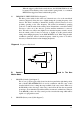
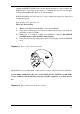
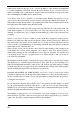
iii. FREQUENCY SHIFT SWITCH (I in diagram 7).
This three position switch found on the rear of the main case, close to the search head
connector (diagram 8) allows the user to slightly change the operating frequency of the
detector. This allows cancelling of interference (beating) caused by detectors in close
proximity operating on the same frequency. The normal (recommended) operating
position is '2', with the switch in the central position. If interference occurs then it will be
necessary to select one of the other two positions until the interference is removed.
Note: The audio tone will become slightly lower when the frequency switch is moved
from the central position. It may be necessary to slightly re-set the ground exclude
setting when changing frequency in the NON MOTION mode. When using the mini
searchhead operate the detector with the frequency switch in position 2. It will be
necessary to retune the detector when changing frequencies.
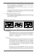
Diagram 8 Frequency Shift Switch
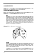
B. Controls Used In The Non
Motion Mode
i. GROUND (Switch) (Q in diagram 7).
This is a two position toggle switch located on the front panel in the right hand position
and is labelled INLAND/BEACH. It is used in conjunction with the rotary control
described in B.ii. below to change the range available on the rotary control. When set to
the INLAND position, the range of the rotary control will work from the most neutral
ground up to more mineralised ground that will be encountered on inland sites. When set
to the BEACH position, the rotary control provides a much wider range which will be
capable of coping with wet sand.
ii. GROUND (Rotary control) (R in diagram 7).
1
2
3