C&T Solution Inc. 12F.-1,No700,Zhongzheng Rd.,Zhonghe Dist., New Taipei City 235,Taiwan(R.O.C) TEL:02-7731-7888 ; FAX:02-7731-7855 CT-MSB01 Intel® Q67 with Core™ i7/ i5 /i3 Micro-ATX Motherboard User’s Manual Ver. 0.
CT-MSB01 User’s Manual Contents Safety Information ................................................................................................................ 4 About this guide.................................................................................................................... 5 Typography ........................................................................................................................... 6 Packing List ............................................................
CT-MSB01 User’s Manual 1.8.3 System Panel (F_PANEL) ...................................................................................................................... 34 1.8.4 ATX power connectors (EATXPWR1) .................................................................................................... 35 1.8.5 Serial Port connectors (COM2, COM3, COM4, COM5, COM6) ............................................................ 35 1.8.6 Digital IO Connector (JDIO1) .....................................
CT-MSB01 User’s Manual Safety Information Electrical safety To prevent electrical shock hazard, disconnect the power cable from the electrical outlet before relocating the system. When adding or removing devices to or from the system, ensure that the power cables for the devices are unplugged before the signal cables are connected. If possible, disconnect all power cables from the existing system before you add a device.
CT-MSB01 User’s Manual Safety Declaration This device complies with the requirements in Part 15 of the FCC rules. Operation is subject to the following two conditions: This device may not cause harmful interference. This device must accept any interference received, including interference that may cause undesired operation. About this guide This user guide contains the information you need when installing and configuring the motherboard.
CT-MSB01 User’s Manual Conventions used in this guide To make sure that you perform certain tasks properly, take note of the following symbols used throughout this manual. DANGER/WARNING: Information to prevent injury to yourself when trying to complete a task. CAUTION: Information to prevent damage to the components when trying to complete a task. IMPORTANT: Instructions that you MUST follow to complete a task. NOTE: Tips and additional information to help you complete a task.
CT-MSB01 User’s Manual Packing List Before you begin installing your single board, please make sure that the following materials have been shipped: 1 x CT-MSB01 Micro-ATX Main board 1 x CD-ROM contains OS drivers 1 x COM cable 2 x SATA cable 1 x I/O Shield 1 x Startup Manual If any of the above items is damaged or missing, please contact your retailer.
CT-MSB01 User’s Manual Revision History Revision V 1.
CT-MSB01 User’s Manual Specifications Summary Specifications System CPU Intel LGA1155 socket supports Intel Core i7/ i5/ i3 CPU BIOS AMI 16Mb SPI System Chipset Intel® Q67 I/O Chipset Nuvoton NCT6776F Memory Four 240-pin UDIMM sockets support up to 16GB dual channel DDR3 1066/ 1333 SDRAM Watchdog Timer Reset: 1 to 255 sec/min per step H/W Status Monitor Monitoring temperature, voltage and cooling fan status. Auto throttling control when CPU overheats.
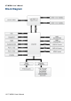
CT-MSB01 User’s Manual Block Diagram 10 CT-MSB01 User’s Manual
CT-MSB01 User’s Manual This chapter describes the motherboard features and the new technologies it supports.
CT-MSB01 User’s Manual Chapter 1 - Product Introduction 1.1 Product highlights 1.1.1 Product Overview Supports latest Intel LGA 1155 CPU-socket interface processor, the 2nd Generation Intel® Core i3, i5, i7 desktop processors which are built on 32 nm technologies to provide smart performance and responsiveness on executing tasks, It combines the CPU and GPU to offer fantastic HD media and graphics, especially on 3D gaming experience.
CT-MSB01 User’s Manual -WindRiver -Redhat -Novell -Green Hills -QNX - LinuxWorks 1.1.3 Key Architecture Features • Supports Intel LGA 1155 CPU, the 2nd Generation Intel® Core i3, i5, i7 desktop processors. -32nm monolithic die -Integrated Gfx (Intel® HD Graphics 3000/2000) & memory controller -4 &2 Cores, up to 6MB LLC -HW accelerated video CODECs - Compatible with high speed DDR3-1333 -PCIe* (CPU): Gen 2.
CT-MSB01 User’s Manual - PCI Express® x 1Gen 2 5GT/s - PCI 2.3 interface - Six SATA ports (2 port of Gen 2.0 and 4 ports of Gen 3.0) support RAID 0,1, 5, 10 - Gigabit Ethernet Media Access Controller (GbE MAC) IPv4 and IPv6 Checksum Offload - High Definition Audio - USB: Gen 2.0, up to 14 ports - SMBus 2.
CT-MSB01 User’s Manual 1.3 Motherboard Overview Before you install the motherboard, study the configuration of your chassis to ensure that the motherboard fits into it. Refer to the chassis documentation before installing the motherboard. Make sure to unplug the power cord before installing or removing the motherboard. Failure to do so can cause you physical injury and damage motherboard components. 1.3.
CT-MSB01 User’s Manual 1.3.3 Motherboard Layout 1.3.
CT-MSB01 User’s Manual Jumpers Label Function Note Page JCMOS1 Clear CMOS 3 x 1 header, pitch 2.54mm 27 PSON1 AT/ATX Mode Select 3 x 1 header, pitch 2.54mm 28 Note Page Rear Panel Connector Label Function KBMS PS/2 Keyboard and Mouse 6-pin Mini-Din 29 COM1 COM1 Connector D-sub 9-pin, male 29 DP1 DisplayPort Connector DisplayPort VGA1 VGA Port D-sub 15-pin, female 29 HDMI1 HDMI Port HDMI 1.3 19-pin 29 LAN1USB12 RJ-45 Ethernet Connector x 1 USB 2.
CT-MSB01 User’s Manual USB910 USB1112 1.4 Central Processing Unit (CPU) The motherboard comes with a surface mount LGA1155 socket designed for the Intel® Core™ i7/ i5/ i3 processor in the 1155-land package. Your boxed Intel® Core™ i7/ i5/ i3 LGA1155 processor package should come with installation instructions for the CPU, fan and heatsink assembly. If the instructions in this section do not match the CPU documentation, follow the latter.
CT-MSB01 User’s Manual Before installing the CPU, make sure that the socket box is facing towards you and the load lever is on your left. 2. Press the load lever with your thumb (A), then move it to the left (B) until it is released from the retention tab. Retention tab A Load lever B To prevent damage to the socket pins, do not remove the PnP cap unless you are installing a CPU. 3.
CT-MSB01 User’s Manual B A 4. Position the CPU over the socket, making sure that the gold triangle is on the top-left corner of the socket then fit the socket alignment key into the CPU notch. Gold triangle CPU notch Alignment key 5. Pull back the load lever , then push the load lever (A) until it snaps into the retention tab. A The CPU fits in only one correct orientation. DO NOT force the CPU into the socket to prevent bending the connectors on the socket and damaging the CPU! 1.4.
CT-MSB01 User’s Manual assembly to ensure optimum thermal condition and performance. Install the motherboard to the chassis before you install the CPU fan and heatsink assembly. When you buy a boxed Intel® Core™ i7/ i5/ i3 LGA1155 processor, the package includes the CPU fan and heatsink assembly. If you buy a CPU separately, make sure that you use only Intel® certified multi‑directional heatsink and fan.
CT-MSB01 User’s Manual 2. Push down two fasteners at a time in a diagonal sequence to secure the heatsink and fan assembly in place. A B B A A B B A 3. Connect the CPU fan cable to the connector on the motherboard labeled CPU_FAN. FAN 1 CPU FAN Do not forget to connect the fan cables to the fan connectors. Insufficient air flow inside the system may damage the motherboard components. These are not jumpers! DO NOT place jumper caps on the fan connectors. 1.4.
CT-MSB01 User’s Manual 3. Pull up two fasteners at a time in a diagonal sequence to disengage the heatsink and fan assembly from the motherboard. A A B B B A B A 4. Carefully remove the heatsink and fan assembly from the motherboard.
CT-MSB01 User’s Manual 5. Rotate each fastener clockwise to ensure correct orientation when reinstalling. 1.5 System Memory 1.5.1 Overview The motherboard comes with four 240-pin Double Data Rate 3 (DDR3) Dual Inline Memory Modules (DIMM) sockets. A DDR3 module has the same physical dimensions as a DDR DIMM but has a 240-pin footprint compared to the 240-pin DDR2 DIMM. DDR3 DIMMs are notched differently to prevent installation on a DDR2 DIMM socket.
CT-MSB01 User’s Manual Channel Channel A Channel B Socket DIMMA1 DIMMA2 DIMMB1 DIMMB2 1.5.2 Memory Configurations You may install 1 GB, 2 GB , and 4 GB unbuffered ECC or non-ECC DDR3 DIMMs into the DIMM sockets using the memory configurations in this section. IF you installed four 1GB memory modules, the system may detect less than 3GB of total memory because of address space allocation for other critical functions.
CT-MSB01 User’s Manual DDR3 DIMM notch Unlocked retaining clip 3. Firmly insert the DIMM into the socket until the retaining clips snap back in place and the DIMM is properly seated. Locked retaining clip A DDR3 DIMM is keyed with a notch so that it fits in only one direction. DO NOT force a DIMM into a socket to avoid damaging the DIMM. The DDR3 DIMM sockets do not support DDR DIMMs. DO NOT install DDR2 DIMMs to the DDR3 DIMM socket.
CT-MSB01 User’s Manual 1. Unlock a DIMM socket by pulling the retaining clips outward 2. Align a DIMM on the socket such that the notch on the DIMM matches the break on the socket. 3. Firmly insert the DIMM into the socket until the retaining clips snap back in place and the DIMM is properly seated. 1.5.4 Removing a DIMM 1. Simultaneously press the retaining clips downward to unlock the DIMM. 2. Remove the DIMM from the socket.
CT-MSB01 User’s Manual 1.6.1 Installing an Expansion Card 1. Before installing the expansion card, read the documentation that came with it and make the necessary hardware settings for the card. 2. Remove the system unit cover (if your motherboard is already installed in a chassis). 3. Remove the bracket opposite the slot that you intend to use. Keep the screw for later use. 4. Align the card connector with the slot and press firmly until the card is completely seated on the slot. 5.
CT-MSB01 User’s Manual 1.6.4 PCI Express x 4 slot This motherboard supports one PCI Express x4 slot that complies with the PCI Express specifications. The following figure shows a RAID card installed on the PCI Express x 4 slot. 1.6.5 PCI Express x 1 slot This motherboard supports one PCI Express x 1 slot that complies with the PCI Express specifications. The following figure shows a LAN card installed on the PCI Express x 1 slot.
CT-MSB01 User’s Manual 1.6.6 PCI slot This motherboard supports one PCI slot that complies with the PCI specifications. The following figure shows a audio card installed on the PCI slot. 1.7 Jumpers 1.7.1 Clear CMOS (CMOS1) This jumper allows you to clear the Real Time Clock (RTC) RAM in CMOS. You can clear the CMOS memory of date, time, and system setup parameters by erasing the CMOS RTC RAM data.
CT-MSB01 User’s Manual Normal (Default) Clear CMOS You do not need to clear the RTC when the system hangs due to overclocking. For system failure due to overclocking, use the C.P.R. (CPU Parameter Recall) feature. Shut down and reboot the system so the BIOS can automatically reset parameter settings to default values. 1.7.2 AT/ATX Power Mode Select (PSON1) This jumper allows you to select ATX Mode or AT mode .
CT-MSB01 User’s Manual 1.8 Connectors 1.8.1 Rear panel connectors 1. PS/2 mouse port (green). This port is for a PS/2 mouse. 2. PS/2 keyboard port (purple). This port is for a PS/2 keyboard. 3. Serial connector. This 9-pin COM1 & COM2 port is for serial devices. 4. DisplayPort. This 20-pin DisplayPort connect to a DisplayPort VGA monitor. 5. VGA port. This 15-pin VGA port connects to a VGA monitor. 6. HDMI port. This 19-pin HDMI 1.3 port connects to a HDMI monitor. 7. LAN (RJ-45) port.
CT-MSB01 User’s Manual 1A~2.22A (26.64W max.) at +12V. Connect the fan cables to the fan connectors on the motherboard, making sure that the black wire of each cable matches the ground pin of the connector. FAN 1 CPU FAN FAN 2 System FAN FAN 3 Chassis Fan Do not forget to connect the fan cables to the fan connectors. Insufficient air flow inside the system may damage the motherboard components. These are not jumpers! DO NOT place jumper caps on the fan connectors.
CT-MSB01 User’s Manual 1.8.3 System Panel (F_PANEL) This connector is for a chassis-mounted front panel audio I/O module that supports either HD Audio or legacy AC’97 audio standard. F_PANEL ATX Power Button/Soft-off Button (Pin 6-8 PWRBT) This 2-pin connector is for the system power button. Pressing the power button turns the system on or puts the system in sleep or soft-off mode depending on the BIOS settings.
CT-MSB01 User’s Manual 1.8.4 ATX power connectors (EATXPWR1) The connector is for ATX power supply plugs. The power supply plugs are designed to fit these connectors in only one orientation. Find the proper orientation and push down firmly until the connectors completely fit. EATXPWR1 ATX12V1 Use of a PSU with a higher power output is recommended when configuring a system with more power-consuming devices. The system may become unstable or may not boot up if the power is inadequate.
CT-MSB01 User’s Manual COM2 , COM3 , COM4 , COM5 , COM6 1.8.6 Digital IO Connector (JDIO1) This connector is for 8-bit General purpose I/O function.
CT-MSB01 User’s Manual 1.8.7 Audio Mic.-In & Line-Out Connector (FPAAUD1) This connector is for a chassis-mounted front panel audio I/O module that supports either HD Audio or legacy AC ‘97 (optional) audio standard. Connect one end of the front panel audio I/O module cable to this connector. FPAAUD1 For motherboards with the optional HD Audio feature, we recommend that you connect a high-definition front panel audio module to this connector to avail of the motherboard’s high‑definition audio capability.
CT-MSB01 User’s Manual The S/PDIF out module is purchased separately. 1.8.9 SPI Connector (CN4) Is a point-to-point interface standard, which allows network equipment designers to develop an array of next-generation multi-service switches and routers to support multi-service traffic with aggregate bandwidths up to OC-192 (10 Gb/s) and beyond, enabling them to dramatically increase system performance. TPM 1.8.10 Serial ATA Connector (SATA1, SATA2) These connectors support SATA 3.
CT-MSB01 User’s Manual 1.8.11 Serial ATA Connector (SATA3 , SATA4 , SATA5, SATA6 ) These connectors support SATA 2.0 and are for the Serial ATA signal cables for Serial ATA hard disk drives. SATA1、SATA2 Connect the right-angle side of SATA signal cable to SATA device. Or you may connect the right-angle side of SATA cable to the onboard SATA port to avoid mechanical conflict with large graphics cards. 1.8.12 USB connectors (USB56, USB78, USB910, USB1112,) These connectors are for USB 2.0 ports.
CT-MSB01 User’s Manual Never connect a 1394 cable to the USB connectors. Doing so will damage the motherboard! The USB module is purchased separately.
CT-MSB01 User’s Manual This chapter tells how to change the system settings through the BIOS Setup menus. Detailed descriptions of the BIOS parameters are also provided.
CT-MSB01 User’s Manual Chapter 2 - BIOS Setup 2.1 BIOS Setup Program This motherboard supports a programmable firmware chip that you can update using the provided utility. Use the BIOS Setup program when you are installing a motherboard, reconfiguring your system, or prompted to “Run Setup.” This section explains how to configure your system using this utility. Even if you are not prompted to use the Setup program, you can change the configuration of your computer in the future.
CT-MSB01 User’s Manual 2.1.1 Legend Box The keys in the legend bar allow you to navigate through the various setup menus Key(s) Function Description ← Select Screen ↑↓ Select Item +- Change Option / Field Enter Go to Sub Screen PGDN Next Page PGUP Previous Page HOME Go to Top of Screen END Go to Bottom of Screen F2/F3 Change Colors F7 Discard Changes F8 N/A F9 Load Optimal Defaults F10 Save and Exit ESC Exit 2.1.2 List Box This box appears only in the opening screen.
CT-MSB01 User’s Manual 2.2 BIOS Menu Screen When you enter the BIOS, the following screen appears. The BIOS menu screen displays the items that allow you to make changes to the system configuration. To access the menu items, press the up/down/right/left arrow key on the keyboard until the desired item is highlighted, then press [Enter] to open the specific menu.
CT-MSB01 User’s Manual 2.3 Main Setup This menu gives you an overview of the general system specifications. The BIOS automatically detects the items in this menu. Use this menu for basic system configurations, such as time, date etc. BIOS Information Displays the auto-detected BIOS information. Memory Information Displays the auto-detected system memory System Date The date format is ,,,. System Time The time format is ,,.
CT-MSB01 User’s Manual 2.4 Advanced BIOS Setup Select the Advanced tab from the setup screen to enter the Advanced BIOS Setup screen. You can select any of the items in the left frame of the screen, such as Chipset configuration, to go to the sub menu for that item. You can display an Advanced BIOS Setup option by highlighting it using the keys. All Advanced BIOS Setup options are described in this section. The Advanced BIOS Setup screen is shown below.
CT-MSB01 User’s Manual PCI Bus Driver Version Displays the information of PCI Bus Driver Version . PCI ROM Priority [EFI compatible ROM] In case of multiple option ROMs ( Legacy and EFI compatible), specifies what PCI option ROM to launch. PCI Common Settings PCI Latency Timer [32 PCI Bus Clocks] Allows the PCI Latency Timer to be adjusted. This option sets the latency of all PCI devices on the PCI bus.
CT-MSB01 User’s Manual PERR# Generation [Disable] Enables or disables PCI devices to Generate PERR#. Configuration options: [Disabled] [Enabled] SPERR# Generation [Disable] Enables or disables PCI devices to Generate SPERR#. Configuration options: [Disabled] [Enabled] PCI Express Device Settings Relaxed Ordering [Disable] Enables or disables PCI Express devices Relaxed Ordering Configuration options: [Disabled] [Enabled] Extend Tag If [Enabled] allows device to use 8-bit tag field as a requester.
CT-MSB01 User’s Manual If [Enabled] allows generation of extended synchronization patterns. Configuration options: [Disable][Enabled] 2.4.2 ACPI Settings ACPI Sleep State [S3 (suspend to RAM)] Select the highest ACPI sleep state the system will enter the SUSPEND button is press. Configuration options: [Suspend Disable][S1 (CPU Stop Clock)] [S3 (suspend to RAM )] Resume On RTC Alarm [Disable] Enable or disable system wake on alarm even. When enabled, system will wake upon the hr/min/sec specified.
CT-MSB01 User’s Manual 2.4.3 Trusted computing Trusted computing (TPM) settings. TPM configuration TPM SUPPORT [Disabled] Enable or disable TPM support.
CT-MSB01 User’s Manual 2.4.4 CPU configuration CPU configuration Displays the CPU information Hyper-threading [Enabled] Enable or disable Hyper-threading support. Configuration options: [Disabled] [Enabled] Active Processor Cores [All] Select the numbers of cores in each processor package. Configuration options: [All] [1] [2] [3] [4] [5] [6] [7] It depends on each CPU type. Limit CPUID Maximum [Disable] Disable for Windos XP.
CT-MSB01 User’s Manual Execute Disable Bit [Enable] XD can prevent certain classes of malicious buffer overflow attacks when combined with a supporting OS ( Windows Server 2003 SP1, Windows XP SP2, SuSE Linux 9.2 RedHat Enterprise 3 Update 3.
CT-MSB01 User’s Manual 2.4.
CT-MSB01 User’s Manual 2.4.6 Intel IGO SWSCI OpRegion Intel IGO SWSCI OpRegion configuration DVMT/FIXED Memory [128MB] Select DVMT/FIXED Mode Memory size used by Internal Graphic Device. Configuration options: [128MB][512MB][Maximum] IGO – Boot Type [VBIOS Default] Select the video Device which will be activated during POST. This has no effect if external graphics present.
CT-MSB01 User’s Manual 2.4.7 Intel TXT(LT) Configuration Display Intel Trusted Execution Technology configuration.
CT-MSB01 User’s Manual 2.4.8 USB Configuration USB Configuration Parameters USB Device Display how many devices are connected. Legacy USB Support [Enabled] Enables Legacy USB support. AUTO option disables legacy support if no USB devices are connected. DISABLE option will keep USB devices available only for EFI applications. Configuration options: [Enabled] [Disabled][Auto] EHCI Hand-off [Disable] This is a workaround for OSes without EHCI hand-off support.
CT-MSB01 User’s Manual Configuration options: [Disabled] [Enabled] USB hardware delays and time-outs: USB transfer time-out [20 sec] The time-out value for Control, Bulk, and Interrupt transfers. Configuration options: [1 sec] [5 sec] [10 sec] [20 sec] Device reset time-out [20 sec] USB mass storage device Start Unit command time-out.
CT-MSB01 User’s Manual AMT Help Configuration options: [Disabled] [Enabled] Unconfigure AMT/ME [Disable] Perform AMT/ME unconfigure without password operation. Configuration options: [Disabled] [Enabled] WatchDog Timer [Disable] Enable/Disable WatchDog Timer. Configuration options: [Disabled] [Enabled] When ‘Enabled’, OS and BIOS WatchDog Timers can be set. 2.4.10 Super IO Configuration System Super IO Chip Parameters. Super IO Configuration Super IO Chip [NCT6776F] 2.4.10.
CT-MSB01 User’s Manual Set Parameters of Serial Port 0 (COMA) Serial Port 0 Configuration Serial Port [Enable] Enable or Disable Serial Port. Configuration options: [Disabled] [Enabled] Device Setting [IO=3F8h; IRQ=4] Change Setting[Auto] Select an optimal setting for Super IO device. Configuration options: [Auto] [IO=3F8h; IRQ=4] [IO=3F8h; IRQ=3, 4, 5, 6, 7, 9. 10, 11, 12] [IO=2F8h; IRQ=3, 4, 5, 6, 7, 9. 10, 11, 12] [IO=3E8h; IRQ=3, 4, 5, 6, 7, 9. 10, 11, 12] [IO=2E8h; IRQ=3, 4, 5, 6, 7, 9.
CT-MSB01 User’s Manual Serial Port 1 Configuration Serial Port [Enable] Enable or Disable Serial Port. Configuration options: [Disabled] [Enabled] Device Setting [IO=2F8h; IRQ=3] Change Setting[Auto] Select an optimal setting for Super IO device. Configuration options: [Auto] [IO=2F8h; IRQ=3] [IO=3F8h; IRQ=3, 4, 5, 6, 7, 9. 10, 11, 12] [IO=2F8h; IRQ=3, 4, 5, 6, 7, 9. 10, 11, 12] [IO=3E8h; IRQ=3, 4, 5, 6, 7, 9. 10, 11, 12] [IO=2E8h; IRQ=3, 4, 5, 6, 7, 9.
CT-MSB01 User’s Manual 2.4.10.3 Serial Port 2 Configuration Serial Port [Enable] Enable or Disable Serial Port. Configuration options: [Disabled] [Enabled] Device Setting [IO=C80h; IRQ=5] Change Setting[Auto] Select an optimal setting for Super IO device. Configuration options: [Auto] [IO=C80h; IRQ=5] [IO=C80h; IRQ=5, 7, 9. 10, 11] [IO=C88h; IRQ=5, 7, 9. 10, 11] [IO=C90h; IRQ=5, 7, 9. 10, 11] [IO=C98h; IRQ=5, 7, 9. 10, 11] 2.4.10.
CT-MSB01 User’s Manual Serial Port 3 Configuration Serial Port [Enable] Enable or Disable Serial Port. Configuration options: [Disabled] [Enabled] Device Setting [IO=C88h; IRQ=5] Change Setting[Auto] Select an optimal setting for Super IO device. Configuration options: [Auto] [IO=C88h; IRQ=5] [IO=C80h; IRQ=5, 7, 9. 10, 11] [IO=C88h; IRQ=5, 7, 9. 10, 11] [IO=C90h; IRQ=5, 7, 9. 10, 11] [IO=C98h; IRQ=5, 7, 9. 10, 11] 2.4.10.
CT-MSB01 User’s Manual Serial Port 4 Configuration Serial Port [Enable] Enable or Disable Serial Port. Configuration options: [Disabled] [Enabled] Device Setting [IO=C90h; IRQ=5] Change Setting[Auto] Select an optimal setting for Super IO device. Configuration options: [Auto] [IO=C90h; IRQ=5] [IO=C80h; IRQ=5, 7, 9. 10, 11] [IO=C88h; IRQ=5, 7, 9. 10, 11] [IO=C90h; IRQ=5, 7, 9. 10, 11] [IO=C98h; IRQ=5, 7, 9. 10, 11] 2.4.10.
CT-MSB01 User’s Manual Serial Port 5 Configuration Serial Port [Enable] Enable or Disable Serial Port. Configuration options: [Disabled] [Enabled] Device Setting [IO=C98h; IRQ=5] Change Setting [Auto] Select an optimal setting for Super IO device. Configuration options: [Auto] [IO=C98h; IRQ=5] [IO=C80h; IRQ=5, 7, 9. 10, 11] [IO=C88h; IRQ=5, 7, 9. 10, 11] [IO=C90h; IRQ=5, 7, 9. 10, 11] [IO=C98h; IRQ=5, 7, 9.
CT-MSB01 User’s Manual 2.4.10.
CT-MSB01 User’s Manual Enable or Disable Resume on PS2 KB Function Configuration options: [Disabled] [Enabled] Resume on PS2 MS[Disabled] Enable or Disable Resume on PS2 MS Function Configuration options: [Disabled] [Enabled] Resume on Ring [Disabled] Enable or Disable Resume on Ring Function Configuration options: [Disabled] [Enabled] Watch Dog Timer [Disabled] Enable or Disable Watch Dog Timer Function Configuration options: [Disabled] [Enabled] 2.4.10.
CT-MSB01 User’s Manual Digital I/O Pin 0 [Input] Configure Digital I/O Pin Configuration options: [Input][Output High][Output Low] Digital I/O Pin 1 [Input] Configure Digital I/O Pin Configuration options: [Input][Output High][Output Low] Digital I/O Pin 2 [Input] Configure Digital I/O Pin Configuration options: [Input][Output High][Output Low] Digital I/O Pin 3 [Input] Configure Digital I/O Pin Configuration options: [Input][Output High][Output Low] Digital I/O Pin 4 [Input] Configure Digital I/O
CT-MSB01 User’s Manual 2.4.
CT-MSB01 User’s Manual 2.4.
CT-MSB01 User’s Manual Out-of-Band Mgmt port [COM0 (Disabled)] Microsoft Windows Emergency management Services (EMS) allows for remote management of a Windows Server OS though a serial port. Configuration options: [COM0 (Disabled)][COM4 (Pci Dev0, Func0) (Disabled)] Terminal Type [VT-UTF8] VT-UTF8 is the preferred terminal type for out-of-band management. The next best choice is VT100+ and then VT100. See above, in Console Rediection Setting page, for more help with Terminal Type/Emulation.
CT-MSB01 User’s Manual ‘start’ signal can be sent to re-start the flow. Hardware flow control uses two wires to send start/stop signals. Configuration options: [None][Hardware RTS/CTS][Software Xon/Xoff] Microsoft Windows Emergency management Services (EMS) allows for remote management of a Windows Server OS though a serial port. Configuration options: [COM0 (Disabled)][COM4 (Pci Dev0, Func0) (Disabled)] 2.
CT-MSB01 User’s Manual 2.5.1 North Bridge Memory Information Display Memory Information Low MMIO Align[1024M] Low MMIO resources align at 64MB/1024MB Configuration options: [64MB][1024MB] DMI Gen2 [Enable] Set DMI Gen2 Enable or Disable Configuration options: [Disabled] [Enabled] VT-d [Disable] Set VT-d Enable or Disable Configuration options: [Disabled] [Enabled] Internal Graphic Adapter [PEG/IGD] Select which graphics controller to use as the primary boot device.
CT-MSB01 User’s Manual IGD Memory IGG share memory size Configuration options: [Disable][32M] [64M] [96M] [128M] [160M] [192M] [224M] [256M] [288M] [320M] [352M] [384M] [416M] [448M] [480M] [512M] Render Standby [Enable] Enable/Disable Render standby by internal graphics device. Configuration options: [Disabled] [Enabled] IGD Multi-Monitor [Disable] Enable/Disable IGD Multi-Monitor by internal graphics device.
CT-MSB01 User’s Manual SMBus Controller [Enable] Enable/Disable SMBus controller. Configuration options: [Disabled] [Enabled] LAN1 Controller [Enable] Enable/Disable LAN1 Controller Configuration options: [Disabled] [Enabled] LAN1 Option-ROM [Disable] Enable/Disable LAN1 boot option for legacy network devices.
CT-MSB01 User’s Manual LAN2 Option-ROM [Disable] Enable/Disable LAN2 boot option for legacy network devices. Configuration options: [Disabled] [Enabled] Wake on LAN2 from S5 [Disable] Configuration options: [Disabled] [Enabled] Restore AC Power Loss [Power Off] Specify what state to go to when power is re-applied after a power failure(G3 state).
CT-MSB01 User’s Manual PCI Express Port 1 Enable/Disable PCI Express Port 1 Configuration options: [Disabled] [Enabled][Auto] PCI Express Port 7 Enable/Disable PCI Express Port 7 Configuration options: [Disabled] [Enabled][Auto] PCIe Sub Decode [Disable] Enable/Disable PCIe Sub Decode Port. ( This option is available when subtractive decode agent Enable (PCHTrap9[14] = ‘1b’) Configuration options: [Disabled] [Enabled][Auto] 2.5.2.
CT-MSB01 User’s Manual EHCI controller 1 [Enabled] Enable/Disable USB 2.0(EHCI) support Configuration options: [Disabled] [Enabled] EHCI controller 2 [Enabled] Enable/Disable USB 2.
CT-MSB01 User’s Manual 2.5.
CT-MSB01 User’s Manual 2.6 Boot Boot Configuration Setup Prompt Timeout [1] Number of seconds to wait for setup activation key. 65535(0xFFFF) means indefinite waiting. Bootup NumLock State [On] Select the keyboard NumLock state Configuration options: [On] [Off] Quick Boot [Disable] Configuration options: [Disable] [Enable] Fast Boot [Disable] Enable or disable boot with initialization of minimal set of devices required to launch active boot option. Has no effect for BBS boot options.
CT-MSB01 User’s Manual CSM16 Module Version [07.64] Display CSM16 Module Version. GataA20 Active [Upon Request] Upon Request – GA20 can be disable using BIOS services. Always – do not allow disabling GA20; this option is useful when any RT code is ececuted above 1MB. Configuration options: [Upon Request] [Always] Option ROM Messages [Force BIOS] Set display mode for option ROM.
CT-MSB01 User’s Manual 2.
CT-MSB01 User’s Manual 2.8 Save & Exit Save changes and Exit Exit system setup after saving the changes. Discard changes and Exit Exit system setup without saving the changes. Save changes and Reset Reset the system after saving the changes. Discard changes and Reset Reset the system without saving the changes. Save changes Save changes done so for to any of the setup option.
CT-MSB01 User’s Manual Discard changes done so for to any of the setup option. Restore Defaults Restore/Load default values for all the setup option. Save as User Defaults Save the changes done so far as User Defaults.