
Call Systems

BF360-12 (12 V DC, 2 A) & BF360-24 (24 V DC, 1.5 A)
EN54-4 Boxed Power Supply Units (PSU) Installation Instructions
FIRE ALARM
ancillaries
1 of 2
Approved Document No. DFU0360000 Rev 7
THIS EQUIPMENT MUST ONLY BE INSTALLED AND MAINTAINED BY A SUITABLY SKILLED AND TECHNICALLY
COMPETENT PERSON. THE PSUS ARE CLASS 1 EQUIPMENT AND MUST BE EARTHED.
BF360-12 and BF360-24 are boxed Mains to regulated DC power supplies providing 2 A @ 12 Vdc (BF360-12) and
1.5 A @ 24 Vdc, (BF360-24). Combining the functions of power supply units, battery charging units and battery
monitoring units, they are fully compliant with the current edition of EN54-4.
INSTALLATION
Location
The power supplies must be sited indoors on a dry, flat surface in an area that is well ventilated. Ideally the panel
indicators should be at eye level and the ambient light level should allow the status of the indicators to be clearly seen.
Mounting
Using the five mounting holes provided, mount the plastic base securely onto a wall. Assess the condition and
construction of the wall and use suitable screw fixings. The mounting holes are suitable for use with No.8-10 or
4-5 mm countersunk screws. Any dust or swarf created during the mounting process must be kept out of the enclosure
and care must be taken not to damage any wiring or components.
Wiring and Cable Entry
All wiring should be installed in accordance with the current edition of the IEE Wiring Regs (BS7671), or the
relevant national standards. The requirement for the Mains supply to the panel is fixed wiring, using 3-core cable
(no less than 1 mm
2
and no greater than 2.5 mm
2
), or a suitable three conductor system fed from an isolating
switched spur fused at 3 A.
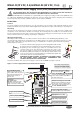
In order to maintain cable segregation, the incoming Mains cable should
be fed into the power supply via the top right-hand side of the enclosure.
Depending on the enclosure type, either cut out suitable holes in the
enclosure using a hole saw, directed by a pilot bit in the centre of the
hole saw (see right) or, remove knock outs with a sharp, light tap using a
flat 6mm broadsided screwdriver (see left). Always ensure that if a hole
is cut out, or knocked out, it is filled with a good quality cable gland. Any
unused holes must be securely blanked off.
WARNING: DO NOT ATTEMPT TO CONNECT THE MAINS SUPPLY
TO THE POWER SUPPLY UNLESS ALL COMPONENTS ARE
SECURELY INSTALLED IN ITS ENCLOSURE!
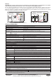
Terminate the Mains cable at the power supply’s connector block CONN1 (see Figure 1 below).
DO NOT
ADJUST VR1
L N
BATTERY FUSE
3.15AF F2
CONN4
FAULT RELAY
CONN3
CONN1
+v
Battery
0v
+v
Output
0v
PLK1
NO NCC
PLK2
PL2
Temp
PL1
Display
off
Cha
rge
0v
CONN5
PRIMARY
F
USE F1
1ATH
250V
HRC
Mains Input Terminals (CONN1)
L = Live, N = Neutral, = Earth
CLASS 1 EQUIPMENT MUST BE EARTHED
Connect incoming Mains earth wire
to the earth terminal and NOT to
the base earth post.
Hazardous Voltages Present LED
When lit red, hazardous voltages
are present on the components
and copper in the shaded area of
the PCB. DO NOT TOUCH!
Control Links (PLK1 & PLK2)
If battery NOT used, fit PLK2 link.
Display Connector (PL1)
High Temp. Output (PL2)
Charge Off Input (CONN5)
Incoming Mains Cable
Must be segregated from
other cables and only enter
the panel through the top
right-hand cut outs or
knock outs.
PSU Earth Strap
DO NOT operate the PSU
without connecting this
strap to the base earth post.
Supply Output (CONN3)
Battery Input (CONN3)
Fault Relay (CONN4)
Figure 1 - Power Supply PCB Layout and Connection Details
See Technical Specification
overleaf for further details
VdS