
User guide
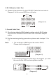

2. RJ11 Modular Cable Test
2.1 Please follow directions for the UTP/STP Cable Test and refer to
Diagram 4 for the correct LED pin out display
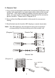
3. Coaxial Cable Test
3.1 Plug the two attached BNC adapter cables on both RJ45 jacks.
Then connect the tested cable to each end of the BNC adapter
cables
3.2 For the remaining testing procedures, please refer to steps 1.2 to
1.5
Note: 1. The center pin of BNC should be read on LED 2.
Please refer to diagram 5.
2. As Coaxial cable has only two wires, we suggest you read
the result of the LED scan using Manual mode.
RJ11
123456
12345678G
RJ45
12345678G
BNC CENTER PIN
BNC SHIELDING
4
(Diagram 4)
(Diagram 5)
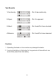
(Diagram 6)
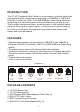
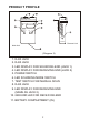
TRENDnet
TEST PIN-OUT INDICATOR
AUTO
MANUAL
ONOFF
12345678G
TC-NT1
Network Cable Tester