
User guide
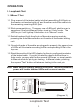
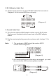

II. Remote Test
1. Plug one end of the tested cable to the transmitting RJ45 jack on the
master unit marked with a ' ' and plug the other end into the remote
terminator. If the tested cable is installed in a patch panel or wall
plate, you may use the included patch cable to solve the connector
gender problem. Please refer to Diagram7 & 8.
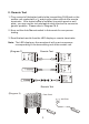
2. Now, set the Auto/Manual switch to Auto mode for one-person
testing.
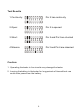
3. Read the test results from the LED display on remote terminator.
Note: The LED display on the remote unit will scan in sequence
corresponding to the transmitting end of the master unit.
Remote Test
5
(Diagram 7)
TRENDnet
TEST PIN-OUT INDICATOR
AUTO
MANUAL
ONOFF
12345678G
TC-NT1
Network Cable Tester
TRENDnet
TEST PIN-OUT INDICATOR
AUTO
MANUAL
ONOFF
12345678G
TC-NT1
Network Cable Tester
TRENDnet
Remote
Terminator
1
2
3
4
5
6
7
8
GND
NOT FOR
LIVE CIRCUITS
TRENDnet
TEST PIN-OUT INDICATOR
AUTO
MANUAL
ONOFF
12345678G
TC-NT1
Network Cable Tester
TRENDnet
Remote
Terminator
1
2
3
4
5
6
7
8
GND
NOT FOR
LIVE CIRCUITS
TRENDnet
TEST PIN-OUT INDICATOR
AUTO
MANUAL
ONOFF
12345678G
TC-NT1
Network Cable Tester
Remote Test
Patch Panel
Wall Plate
(Diagram 8)