
Manual

DB-525
Front Panel 5.25 inch Device Bay
Installation Guide
Step 1
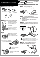
Check the contents of the Box.
Front Connect DB-525
metal frame with P.C.B
DB-525
plastic cover 1
for HDD
DB-525
plastic cover 2
for MO/FDD/Zip
Installation guide
Screws
R NT
2.Insert your DB-525 into the slot,
Do not force it in any further than
needed.
Step 2
Remove the cover case from the computer.
Please check that everything
connected to the computer has
been removed and that the
computer itself has been
switched off from the main
power supply.
Please consult the computer manual
when remove the cover case from the
computer.
Caution:Please be careful when
removing the cover case as all edges
are sharp.
3.Please use the screws
provided to lock the DB-525
into place.
Step 4
Step 5-2
Step 5-1
Step 5
Connect the FireWire cable.
(For IEEE-1394 host adapter with 6pin connector.)
Locate the FireWire 6pin-plug cable in the package.
Connect the USB 2.0 interface cable.
(For built-in internal USB 2.0 or 1.1 connector on mainboard.)
Locate A-to-5pin type USB cable in the package.
Connect the USB interface cable.
(For USB 2.0 host adapter with A-type connector)
For built-in internal USB 2.0 or 1.1 connector on mainboard:
refer to Step 5-1.
For USB 2.0 host adapter with A-type connector:
refer to Step 5-2.
To connect the USB cable from the main board, please check your
mainboard manual and page 2 of this manual for further
connection instruction.
Caution:The USB port may be damaged if inserting USB flat
cable on reverse.(Warranty does not cover such damage)
Caution:For easy installation,
connect the USB & FireWire
cables to DB-525 before insert
it into the slot.
Step 3
Install DB-525 to the computer.
1.Remove the 5.25-inch panel.
Further details on how to
remove the panel can be found
in your computer
NNECT
Connect the USB 2.0 or 1.1 interface cable.
Internal USB Port
Internal IEEE 1394 Port
USB Power
USB P3-
USB P3+
GND
USB Power
USB P2-
USB P2+
GND
NC
16
ASUS
10 5
Internal USB Port