SW404HD | SW808HD High Definition Matrix Switch SW404HD Matrix SW808HD Matrix
Matrix Switching System—Instruction Manual Before You Use the System 1. Read manual Carefully read the manual.. 2. Installation environment The system should be installed indoors only. Install either in a sturdy rack or on a table in a well-ventilated place. 3. Lightning Unplug the power cord during lightning or after prolonged period of non-use to avoid damage to the equipment. 4.
Matrix Switching System—Instruction Manual Software Description ............................................................................................... 15 Software Activation.................................................................................................. 15 Software Features ................................................................................................... 15 Main Operation Interface Functions .....................................................................
Matrix Switching System—Instruction Manual Page 1 Matrix System Overview Matrix System The Matrix Switch is a high performance system used to switch audio/video frequencies. It will cross switch multiple input/output audio/video signals through independent Y/Pb/Pr component and audio input/output terminals.
Page 2 Matrix Switching System—Instruction Manual Matrix System Front/Rear Panels Model SW404HD Front/Rear Panels SW404HD Front Panel SW404HD Rear Panel Model SW808HD Front/Rear Panels
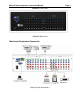
Matrix Switching System—Instruction Manual Page 3 SW808HD Front Panel SW808HD Rear Panel Matrix and Peripherals Connection Receiver Matrix System Connections
Page 4 Matrix Switching System—Instruction Manual Input/Output Jacks Dependent on the matrix model installed, the video signal input/output jacks are arranged in either 4 or 8 columns of RCA female connectors. The connector rows from top to bottom are: Y video (green), Pb/Cb video (blue), Pr/Cr video (red), right audio signal (red), and left audio signal (white). The input and output jack channels are numbered from left to right as 1 to 8 (or 1 to 4).
Matrix Switching System—Instruction Manual Page 5 Connection Method The audio inputs and outputs can be separately connected to audio signal connectors of video recorders and multiplexers. Use the RCA cables for connecting AV equipment to the matrix. Connect the video and audio connectors of the signal source equipment output terminals to the same channel connector of the matrix input terminals. Connect the output of the matrix switch to the input connectors of the interfaced equipment.
Page 6 Matrix Switching System—Instruction Manual RS-232 Communication Port Connection Methods The RS-232 port is a 9-pin female connector. The pin functions are shown in the following table and connections in the Illustrations below: Note: The Matrix RS-232 port is defined as DCE.
Matrix Switching System—Instruction Manual Page 7 RS-485 Communication Port Connection Methods The RS-485 port will control more than one product. The RS-485 Port is shown below. On/Off Switch Settings A. DIP switch 8:(RS-232/RS-485 on/off) ON:RS-232 enables single system or RS-485 serial master OFF:RS-485 enables RS-485 serial slave B. B. DIP switches 6 and 7 (RS-485 - terminator on/off) ON enables Terminator OFF disables Terminator C.
Page 8 Matrix Switching System—Instruction Manual ID Address (Decimal) 9 10 11 12 13 14 15 16 17 18 19 20 21 22 23 24 25 26 27 28 29 30 31 ID Address Settings ON/OFF Switch Settings Software ID ON/OFF Address (Binary) SW1 SW2 SW3 SW4 SW5 (Hexadecimal ) 09 0A 0B 0C 0D 0E 0F 10 11 12 13 14 15 16 17 18 19 1A 1B 1C 1D 1E 1F 01001 01010 01011 01100 01101 01110 01111 10000 10001 10010 10011 10100 10101 10110 10111 11000 11001 11010 11011 11100 11101 11110 11111 off off off off off off off on on on on on on o
Matrix Switching System—Instruction Manual Page 9 Matrix System and Control System Connection - RS-232 PC RS-232, multi-Matrix (up to 32) connections are as shown below. NOTES: 1. For RS-232 connections refer to photo below. 2. RS-232 or RS-485 baud rates: 9600bps, 8-bit data transmission address, no, odd, or even parity, 1-bit stop address: (9600 - 8 - N - 1). 3. Serial connection between Matrix RS-485 as follows: TX (+) ↔ TX (+) TX (-) ↔ TX (-) RX (+) ↔ RX (+) RX (-) ↔ RX (-) 4.
Page 10 Matrix Switching System—Instruction Manual Matrix System and Control System Connection - RS-485 PC RS-485, multi-Matrix (up to 32) connections are as shown below. NOTES: 1. RS-485 baud rate: 9600bps, 8-bit data transmission address, no, odd, or even parity 1bit stop address: (9600 – 8 - N - 1). 2. Connect PC RS-485 port to the Matrix RS-485 port Î: TX (+) ↔ TX (+) TX (-) ↔ TX (-) RX (+) ↔ RX (+) RX (-) ↔ RX (-) 3.
Matrix Switching System—Instruction Manual Page 11 Matrix Control Panel Operation Input/Output Switching Key Operation Mode The front panel keys of the Matrix system are used for fast audio/video switching (for details refer to the Front Panel Key Functions). Operation Operation consists of three basic steps: Choose the Switching Method Select the Output Channel Select the Input Channel.
Page 12 Part 4 5 6 7 8 9 Matrix Switching System—Instruction Manual Front Panel Key Functions Function Key Function Implement all output selection keys via certain input route. Example: First press the ALL key, then select the input channel to output ALL to all output channels; first press the ALL key, then press the OFF key to close all the presently displayed switching status. Close output channel key.
Matrix Switching System—Instruction Manual Page 13 Operation Examples Example 1: Synchronously connect the number 1 audio/video input signals to the number 3 and 4 output channels (Audio and Video enabled). Key Operation Example 1 LCD Display OUTPUT INPUT OUTPUT INPUT Operation 1. Press the OUT number 3 key (output channel). 2. When the LCD number(s) under the 3 on the panel begins to flash press the IN number 1 key The LCD shows 1 at channel number 3 for both Audio and Video. 3.
Page 14 Matrix Switching System—Instruction Manual Key OUTPUT INPUT OUTPUT INPUT OUTPUT INPUT Operation Example 2 LCD Display Operation 4. Press the OUT number 3 key (output channel). 5. When the Video LCD number under the 3 on the panel begins to flash press the IN number 4 key The LCD shows 4 at channel number 3 for video only. 6. Press the OUT number 5 key (output channel). 7.
Matrix Switching System—Instruction Manual Page 15 Matrix Application Software Software Introduction The (AV Matrix) Matrix control software is used to remotely configure one or more of the SW404HD or SW808HD matrix switches. Software Description The AV Matrix testing software application tool is used for matrix testing and application. The following is the required PC operation environment.
Page 16 Matrix Switching System—Instruction Manual Use the lower scroll bar to view additional columns Examples for Selecting Matrix Switching Functions: Example 1 (Audio and Video Switching): Using a SW808HD matrix having all the input/output ports properly connected to the equipment.
Matrix Switching System—Instruction Manual Page 17 Step 2: First select the Output number keys 02, 03 and 05 to the right, and select the Input number key 01 to the bottom. Then, consecutively press the previously selected Output number keys 02, 03 and 05 (or press the Deselect all output key). This selects Input 01 to be routed to Outputs 02, 03, and 05. Step 3: First select the Output number key 06 to the right, and select the Input number key 03 to the bottom.
Page 18 Matrix Switching System—Instruction Manual Disconnect Function Keys Close all the unused output ports.
Matrix Switching System—Instruction Manual Page 19 Example: Close the output ports 03, 05, and 06. Step 1: First press down the output number keys 03, 05 and 06 to the right Step 2: Press the Disconnect key Step 3: Press the previously pressed output number keys 03, 05 and 06 (or press the Deselect all output key) to complete the operation.
Page 20 Matrix Switching System—Instruction Manual Disconnect all: Command Function Description Use this command to close all the switching paths at one time. Press the Disconnect all key to close connection to all input and output ports. Memory Function Usage Store and Retrieve Function Description The Store Function saves all the present input/output switching relations to any Locations from #1 to #8 desired. The Retrieve Function is used to retrieve these saved input/output switching relations.
Matrix Switching System—Instruction Manual Page 21 Exit Function Description Used to exit the operating software. Other Usages Displays the presently saved switching status as shown below: This table shows the Video/Audio Input ports corresponding to the Output ports. When a port is closed, ZERO will be shown in that box. Communication Protocol and Control Command Code Communication Protocol: Baud rate 9600bps No, odd, or even parity 8-bit transmission address 1 bit stop address.
Page 22 Parameters Matrix Switching System—Instruction Manual Model Impedance SW808HD 75 ohms Video Output Connector Signal Strength Impedance 8 RCA Female Connectors 2.5Vp-p 75 ohms Audio Signal Input/Output Connectors Signal Type Impedance Max. Input Level Max. Output Level Control Type Serial Control Connectors Baud Rate and Protocol SW404HD 4 RCA Female Connectors RCA Female Connectors Stereo, Balanced or Unbalanced Input: l0k-ohms Output: 100-ohms +19.5dBu +19.
Matrix Switching System—Instruction Manual Page 23 Common Problems and Solutions 1. The matrix front panel switching keys not responsive? Answer: The matrix front panel keys employ scanning testing and require longer response time. Press the keys for 2 seconds and then release. This way, key switching will be responsive in operation. 2. The matrix does not display or color display is abnormal after hot plug? Answer: Switching of the signals goes through the matrix ICs.
Page 24 Matrix Switching System—Instruction Manual 10. The matrix panel keys and communication ports are out of order? Answer: Check if the equipment power input is good and the computer communication ports are good. If the connections are good, it could be failure of the product. Call 469-429 9200 for technical support. 11. Operation and function failure occurred? Answer: Check if the equipment and the matrix system are properly connected. If the problem persists, Call 469-429 9200 for technical support.
Matrix Switching System—Instruction Manual Page 25 APPENDIX – Matrix Switch Communication Protocol The RS-232/RS-485 communications are half-duplex with variable byte count packets. For RS-232, the matrix switch operates as a DCE device and therefore can be connected using a straight cable to a DTE device such as a computer. The RS-232 connector is a DB-9 female. For RS-485, a discrete wiring connector is provided for custom connection to any RS-485 equipment.
Page 26 Matrix Switching System—Instruction Manual Protocol Description Command Packet Command packets are sent to the Matrix Switch from a computer and are 4 or more bytes long depending upon the instruction code.
Matrix Switching System—Instruction Manual Address Byte (Command Type A and B) 7 6 5 4 BT X CRC M4 Broadcast Reserved CRC BT: Broadcast Page 27 3 2 1 M3 M3 M1 Machine ID (5-bit address) 0 M0 0: Instruction for one machine with matching Machine ID 1: Instruction for all machines If BT = 1, machine will not return a response packet.
Page 28 Matrix Switching System—Instruction Manual Response Packet Byte Descriptions ACK Type A ACK Byte CRC ACK Byte (ACK Type A, B, and C) 7 6 5 4 3 2 ACC X X M4 M3 M3 Accept Reserved Reserved Machine ID (5-bit address) ACC: Accept: 1 Ml 0 MO 0: Reject received command 1: Accept command ACK Type B ACK Length Byte Byte Output Byte 1 Input Byte 1 Output Byte n === Input Byte n Length Byte (ACK Type B) L7 L6 L5 L4 L3 L2 L1 Number of Output and Input Bytes to follow not including CRC Output Byte
Matrix Switching System—Instruction Manual Page 29 Supported Output Port (ACK Type C) SOP7 SOP6 SOP5 SOP4 SOP3 SOP2 Bit = 1 if output port is supported, else 0 SOP1 SOP0 Supported Input Port (ACK Type C) SIP7 SIP6 SIP5 SIP4 SIP3 SIP2 Bit = 1 if output port is supported, else 0 SIP1 SIP0 Machine Name Bytes (ACK Type C) MN7 MN6 MN5 MN4 MN3 MN2 ASCII Code (character) MN1 MN0 Command Table HEX Instruction Variable Instruction Description Length Code 00h Dummy Call N Output Byte Input Byte Note AC
Page 30 Matrix Switching System—Instruction Manual HEX Instruction Variable Instruction Description Length Code Output Byte 08h Request Status of Audio Output Y Input Byte Audi output for Memory requested Location # to get status, (1-8,0= status from all) Note ACK Type 1,2 B Request N 00h 00h 1 C Machine Info and Model Command Note: 1. Not supported for Broadcast command. 2. Memory # 0 is current switching status, memory # 1-x is free location.
Matrix Switching System—Instruction Manual Page 31 Trademarks All the companies, brand names, and product names referred to this manual are the trademarks or registered trademarks belonging to their respective companies. Warranty Cable Electronics, Inc. warrants this product to be free from defects in material and workmanship, under normal use and service, for a period of one year from the purchase by the original purchaser.