
User Manual


4
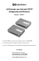
A/V Extender over Cat6 with TCP/IP Configuration and IR Control
www.cablematters.com
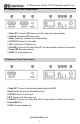
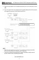
3.2 Transmitter Panel Connections
1. Video OUT : Connect to the remote extended display with HDMI
2. Reset: Restart the Receiver with default settings
3. CAT IN: RJ45 port for Cat 6 cable
4. IR-R: 3.5mm port for IR receiver cord
5. Link LED: Connect a Cat 6 cable. Blue LED Link status indicator verifies a live connection
6. Power LED: Blue
7. DC/5V: AC power adapter port.
1. Video OUT : Connect HDMI display mirror the output of the remote displays
2. Video IN: Connect to HDMI video source
3. Reset: Restart the Transmitter with default settings
4. CAT OUT: RJ45 port for Cat 6 cable
5. IR-T: 3.5mm port for IR blaster cord
6. Link LED: Connect a Cat 6 cable. Blue LED Link status indicator verifies a live connection
7. Power LED: Blue when powered
8. DC/5V: AC power adapter port.
3.3 Receiver Panel Connections