
- CABLETRON Systems, Inc, SmartSwitch User's Guide 2E42-27, 2E42-27R, 2E43-27, 2E43-27R

Chapter 1:
Introduction
1-2 2E42-27/2E42-27R/2E43-27/2E43-27R User’s Guide
Appendix A,
Specifications
, contains information on functionality and
operating specifications, connector pinouts, environmental requirements,
and physical properties.
Appendix B,
FE-100TX, FE-100FX, and FE-100F3 Specifications
,
contains information about FE-100TX pinouts and information
concerning cable types used with the FE-100FX and FE-100F3.
Appendix C,
Optional Installations and Mode Switch Bank Settings
,
describes how to install optional Fast Ethernet Interface Modules and how
to set the Mode Switch.
1.3 2E4X-27 FEATURES
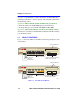
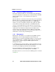
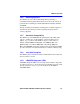
Figure 1-1 shows the 2E42-27 and 2E43-27. Following the figure is a list
of the features.
Figure 1-1 The 2E42-27 and 2E43-27
19601_01
RESET Button
RESET Button
1
2
3
4
5
6
7
8
11
12
13
14
15
16
9
10
17
18
19
20
21
22
23
24
2E42-27
COM
PWR
CPU
RESET
1X 3X 5X 7X 9X 11X 13X 15X 17X 19X 21X 23X
2625
Optional HSIM Slot
COM Port
System LEDs
Port Status LEDs
Network Ports 1 - 24
(RJ45 connectors)
Optional Fast Ethernet Interface
Module Ports 25 and 26
2E43-27
COM
PWR
CPU
RESET
2625
1
2
3
4
5
6
7
8
11
12
13
14
15
16
9
10
17
18
19
20
21
22
23
24
COM Port
System LEDs
Port Status LEDs
Network Ports 1 - 24
(RJ21 connectors)
Optional Fast Ethernet Interface
Module Ports 25 and 26
Optional HSIM Slot