
- CABLETRON Systems, Inc, SmartSwitch User's Guide 2E42-27, 2E42-27R, 2E43-27, 2E43-27R

Appendix C: Optional Installations and Mode Switch Bank Settings
C-4 2E42-27/2E42-27R/2E43-27/2E43-27R User’s Guide
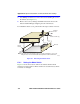
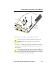
3. Use a Phillips screwdriver to remove the screws attaching the cover to
the chassis. (See Figure C-1.)
4. Remove the cover by sliding it back until it clears the front of the
chassis and then lifting it straight up and off of the chassis.
To reinstall the chassis cover, perform the removal procedures in reverse.
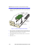
Figure C-1 Removing the Chassis Cover
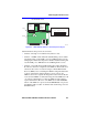
C.2.1 Setting the Mode Switch
Figure C-2 shows the location of the mode switches and the switch
settings for normal operation. These switches are set at the factory and do
not need to be changed.
22511-3
0
Chassis
Cover
Chassis
Cover Screws (7)
Note: If the device was rack mounted, the four screws fastening the cover to the
front panel are removed and installed along with the rackmount brackets.
Front
Panel