
- CABLETRON Systems, Inc, SmartSwitch User's Guide 2E42-27, 2E42-27R, 2E43-27, 2E43-27R

Connecting to the Network
2E42-27/2E42-27R/2E43-27/2E43-27R User’s Guide 3-9
3.4 CONNECTING TO THE NETWORK
This section provides the procedures for connecting UTP and fiber optic
segments from the network or other devices to the 2E4X-27.
Ports 1 through 24 on the 2E42-27 and 2E42-27R have RJ45 connectors
for UTP connections. Ports 1 through 24 on the 2E43-27 and 2E43-27R
have two RJ21 connectors for UTP connections. On all of these devices,
ports 25 and 26 support FE-100TX, FE-100FX, or FE-100F3 Fast
Ethernet Interface Modules.
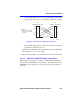
The FE-100TX has an RJ45 connector for a UTP cable connection. The
FE-100FX and FE-100F3 have SC connectors for fiber optic cable
connections.
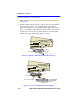
Refer to Section 3.4.1 to make UTP connections to ports 1 through 24.
Refer to Section 3.4.2 to make a UTP connection to an FE-100TX in port
slot 25 or 26.
Refer to Section 3.4.3 to make a fiber optic cable connection to an
FE-100FX or FE-100F3 in port slot 25 or 26.
Refer to the associated High Speed Interface Module user’s guide to make
connections to an optional High Speed Interface Module installed in the
HSIM slot.
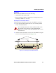
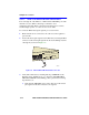
3.4.1 Connecting UTP Cables to Ports 1 Through 24
The 2E42-27 and 2E42-27R use 24 RJ45 connectors for the port 1
through 24 connections. The 2E43-27 and 2E42-27R use two RJ21
connectors for the port connections. Each of the cables connected to these
two ports can have 12 twisted pairs.
NOTE
If the 2E4X-27 is being installed in a network using
SmartTrunking, there are rules concerning the network cable
and port configurations that must be followed for
SmartTrunking to operate properly. Before connecting the
cables, refer to the
SmartTrunk User’s Guide
for the
configuration information.