
- CABLETRON Systems, Inc, SmartSwitch User's Guide 2E42-27, 2E42-27R, 2E43-27, 2E43-27R

Connecting to the Network
2E42-27/2E42-27R/2E43-27/2E43-27R User’s Guide 3-11
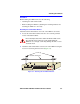
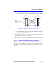
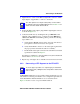
b. Verify that the RJ45 connectors on the twisted pair segment have
the proper pinouts (Figure 3-7) and check the cable for continuity.
Figure 3-7 Cable Pinouts - (RJ45) Crossover Cable
c. Check that the twisted pair connection meets the dB loss and cable
specifications outlined in Chapter 2.
If a link is not established, contact the Cabletron Systems Global Call
Center. Refer to Section 1.6 for details.
4. Repeat steps 1 through 3 above, until all connections have been made.
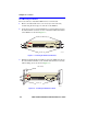
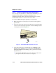
3.4.1.2 2E43-27 or 2E43-27R Cable Connections
When facing the front panel of a 2E43-27 or 2E43-27R, the left RJ21 is
the connector for 10BASE-T ports 1 through 12. The right RJ21 is for the
10BASE-T ports 13 through 24 connections. All 24 ports have internal
crossovers.
TX+
TX–
RX+
RX– 2
1
3
6
TO
10BASE-T Device Port
TX+
TX–
2
1
3
6
NOTE:
RX+/RX– and TX+/TX–
must share a common
color pair.
TO
SmartSwitch RJ45 Port
1574-30
RJ45 to RJ45
RX+
RX–