
- CABLETRON Systems, Inc, SmartSwitch User's Guide 2E42-27, 2E42-27R, 2E43-27, 2E43-27R

Connecting to the Network
2E42-27/2E42-27R/2E43-27/2E43-27R User’s Guide 3-13
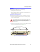
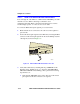
3. Tighten the two screws on the RJ21 straight cable connector or RJ21
angle adapter, as applicable, to secure it to the device.
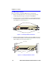
4. If using the RJ21 angle adapter, plug the RJ21 right-angled connector
as shown in Figure 3-9.
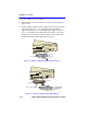
5. Verify that a link exists by checking that the port RX LED is ON
(flashing yellow, blinking green, or solid green). If the RX LED is
OFF and the TX LED is not blinking yellow, perform the following
steps until it is on:
a. Verify that the 10BASE-T device at the other end of the twisted
pair segment is ON and connected to the segment.
b. Verify that the RJ45 connectors on the twisted pair segment have
the proper pinouts and check the cable for continuity.
c. Check that the twisted pair connection meets the dB loss and cable
specifications outlined in Chapter 2.
If a link is not established, contact the Cabletron Systems Global Call
Center. Refer to Section 1.6 for details.
6. Repeat steps 1 through 5 above, until all connections have been made.
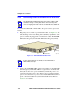
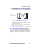
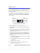
3.4.2 Connecting a UTP Segment to the FE-100TX
An FE-100TX installed in port slot 25 and/or 26 has an internal crossover
switch. When connecting a workstation, use a straight-through cable and
set the Fast Ethernet Interface Module crossover switch shown in
Figure 3-10 to the crossed over position marked with X.
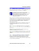
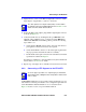
NOTE
The cable pinouts for a 25-pair cable (RJ21) can be found in
the Cabletron Systems
Cabling Guide.
Refer to Section 1.7 for
details on how to obtain this document.
NOTE
To ensure proper operation, use only Category 5 Unshielded
Twisted Pair (UTP) cabling that has an impedance between 85
and 111 ohms.