
- CABLETRON Systems, Inc, SmartSwitch User's Guide 2E42-27, 2E42-27R, 2E43-27, 2E43-27R


Connecting to the Network
2E42-27/2E42-27R/2E43-27/2E43-27R User’s Guide 3-15
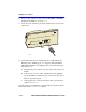
e. Confirm that the crossover switch is in the correct position.
If a link is not established, contact the Cabletron Systems Global Call
Center. Refer to Section 1.6 for details.
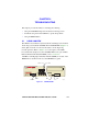
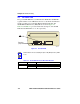
3.4.3 Connecting a Fiber Optic Segment to the
FE-100FX and FE-100F3
The FE-100FX and FE-100F3 have SC style network ports (see
Figure 3-11). Cabletron Systems supplies fiber optic cable that uses SC
style connectors, which are keyed to ensure proper crossover of the
transmit and receive fibers.
Fiber Optic Network Connection
1. Remove the protective plastic covers from the fiber optic ports on the
applicable port on the module and from the ends of the connectors.
NOTES
An odd number of crossovers (preferably one) must be
maintained between devices so that the transmit port of one
device is connected to the receive port of the other device and
vice versa.
If the fiber optic cable being used has SC style connectors that
do not resemble MIC style connectors, or has SC connectors
on one end and a different type on the other, such as ST
connectors, ensure that the proper crossing over occurs.
!
CAUTION
The FE-100F3 uses Class 1 lasers. Do not use optical
instruments to view the laser output. The use of optical
instruments to view laser output increases eye hazard. When
viewing the output optical port, power must be removed from
the network adapter.
!
CAUTION
Do not touch the ends of the fiber optic strands, and do not let
the ends come in contact with dust, dirt, or other contaminants.
Contamination of the ends causes problems in data
transmissions. If the ends become contaminated, blow the
surfaces clean with a canned duster. A fiber port cleaning swab
saturated with optical-grade isopropyl alcohol may also be used
to clean the fiber optic ends.