
- CABLETRON Systems, Inc, SmartSwitch User's Guide 2E42-27, 2E42-27R, 2E43-27, 2E43-27R

Chapter 3: Installation
3-16 2E42-27/2E42-27R/2E43-27/2E43-27R User’s Guide
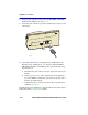
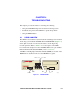
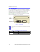
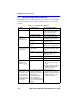
2. Insert one end of the SC connector into the FE-100FX or FE-100F3
installed in the 2E4X-27. See Figure 3-11.
3. At the other end of the fiber optic cable, attach the SC connector to the
other device.
Figure 3-11 FE-100FX and FE-100F3 Ports
4. Verify that a link exists by checking that the port RX LED is ON
(flashing yellow, blinking green, or solid green). If the RX LED is
OFF and the TX LED is not blinking yellow, perform the following
steps until it is on:
a. Check that the power is turned on for the device at the other end of
the link.
b. Verify proper crossover of fiber strands between the applicable
port on the 2E4X-27 and the fiber optic device at the other end of
the fiber optic link segment.
c. Verify that the fiber connection meets the dB loss specifications
outlined in Section 2.4.
If a Link has not been established, contact the Cabletron Systems Global
Call Center. Refer to Section 1.6 for details.
1960-34
RX LED
26
25