
- CABLETRON Systems, Inc, SmartSwitch User's Guide 2E42-27, 2E42-27R, 2E43-27, 2E43-27R

Ethernet Full Duplex Configuration Screen
2E42-27/2E42-27R/2E43-27/2E43-27R User’s Guide 5-39
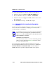
3. Use the arrow keys to highlight the SAVE command at the bottom of
the screen.
4. Press ENTER. The message “SAVED OK” is displayed.
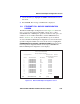
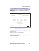
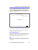
5.11 ETHERNET FULL DUPLEX CONFIGURATION
SCREEN
The Ethernet Full Duplex Configuration screen, Figure 5-18, allows the
user to set ports 1 through 24, individually or all at once, to either
Standard Ethernet or Full Duplex operation, and monitor each port to see
whether or not it is enabled and linked to another 10BASE-T device.
Refer to Section 5.15 to set the Operation Mode for ports 25 and 26.
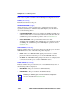
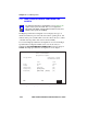
To access the Ethernet Full Duplex Configuration screen from the Device
Specific Configuration Menu screen, use the arrow keys to highlight the
ETHERNET FULL DUPLEX CONFIGURATION menu item in the
Device Specific Configuration Menu screen and press ENTER. The
Ethernet Full Duplex Configuration screen displays.
Figure 5-18 Ethernet Full Duplex Configuration Screen
Firmware Revision: XX.XX.XX
Ethernet Full Duplex Configuration
19601-21
Device Type: 2E42-27
BOOTPROM Revision: XX.XX.XX
PORT #
1
2
3
4
5
6
7
8
9
10
11
12
LINK STATUS
Link
Link
Link
No Link
Link
Link
Link
Link
Link
Link
Link
Link
2E42-27 LOCAL MANAGEMENT
Event Message Line
SAVE
OPERATION MODE
[STANDARD ENET]
[STANDARD ENET]
[STANDARD ENET]
[STANDARD ENET]
[STANDARD ENET]
[STANDARD ENET]
[STANDARD ENET]
[STANDARD ENET]
[STANDARD ENET]
[STANDARD ENET]
[STANDARD ENET]
[STANDARD ENET]
PORT STATUS
ENABLED
ENABLED
ENABLED
ENABLED
ENABLED
ENABLED
ENABLED
ENABLED
ENABLED
ENABLED
ENABLED
ENABLED
SET ALL PORTS: FULL
RETURN
RETURN
[13-24]
EXIT