2E48-27R/2E49-27R SmartSwitch 2200 User’s Guide PWR TX RX RX 17 TX RX 18 TX RX 19 TX RX 20 TX RX 21 TX RX 22 TX RX TX 24 23 RESET COM CPU RX TX RX TX RX TX RX TX RX 1 TX RX TX RX 11 10 9 RX TX RX TX RX TX RX TX RX 13 12 3 2 TX RX TX RX 14 5 4 TX RX TX RX TX 16 15 6 TX 8 7 2E48-27R PWR RX TX RX TX RX TX RX 17 TX RX TX RX TX RX 18 TX RX TX RX TX RX 19 TX RX TX RX TX RX 20 TX RX TX RX TX RX 21 TX RX
Only qualified personnel should perform installation procedures. NOTICE Cabletron Systems reserves the right to make changes in specifications and other information contained in this document without prior notice. The reader should in all cases consult Cabletron Systems to determine whether any such changes have been made. The hardware, firmware, or software described in this manual is subject to change without notice.
Notice INDUSTRY CANADA NOTICE This digital apparatus does not exceed the Class A limits for radio noise emissions from digital apparatus set out in the Radio Interference Regulations of the Canadian Department of Communications. Le présent appareil numérique n’émet pas de bruits radioélectriques dépassant les limites applicables aux appareils numériques de la class A prescrites dans le Règlement sur le brouillage radioélectrique édicté par le ministère des Communications du Canada.
Notice EXCLUSION OF WARRANTY AND DISCLAIMER OF LIABILITY 1. EXCLUSION OF WARRANTY. Except as may be specifically provided by Cabletron in writing, Cabletron makes no warranty, expressed or implied, concerning the Program (including its documentation and media).
Notice SAFETY INFORMATION CLASS 1 LASER TRANSCEIVERS THE FE-100F3 FAST ETHERNET INTERFACE MODULE, FPIM-05 AND FPIM-07 FDDI PORT INTERFACE MODULES, AND APIM-29 ATM PORT INTERFACE MODULE USE CLASS 1 LASER TRANSCEIVERS. READ THE FOLLOWING SAFETY INFORMATION BEFORE INSTALLING OR OPERATING THESE MODULES. The Class 1 laser transceivers use an optical feedback loop to maintain Class 1 operation limits. This control loop eliminates the need for maintenance checks or adjustments.
Notice DECLARATION OF CONFORMITY Application of Council Directive(s): Manufacturer’s Name: Manufacturer’s Address: European Representative Name: European Representative Address: Conformance to Directive(s)/Product Standards: Equipment Type/Environment: 89/336/EEC 73/23/EEC Cabletron Systems, Inc. 35 Industrial Way PO Box 5005 Rochester, NH 03867 Mr. J.
Notice vi 2E48-27R/2E49-27R User’s Guide
CONTENTS CHAPTER 1 INTRODUCTION 1.1 Using This Guide ......................................................................... 1-1 1.2 Structure of This Guide................................................................ 1-1 1.3 2E4X-27R Overview .................................................................... 1-2 1.3.1 Connectivity .................................................................... 1-4 1.3.2 Full Duplex Switched Ethernet........................................ 1-4 1.3.3 SmartTrunk .
Contents CHAPTER 4 TROUBLESHOOTING 4.1 Using LANVIEW...........................................................................4-1 4.2 FE-100TX LED.............................................................................4-4 4.3 Troubleshooting Checklist............................................................4-6 4.4 Using the RESET Button .............................................................4-7 CHAPTER 5 LOCAL MANAGEMENT 5.1 Overview ...........................................................
Contents 5.11 Ethernet Full Duplex Configuration Screen ............................... 5-42 5.11.1 Setting the Operation Mode .......................................... 5-44 5.12 Device Specific Configuration Menu Screen ............................. 5-45 5.13 System Resources Screen ........................................................ 5-47 5.13.1 Setting the Reset Peak Switch Utilization ..................... 5-48 5.14 High Speed Interface Configuration Menu Screen .................... 5-49 5.
Contents APPENDIX B B.1 B.2 B.3 FE-100TX, FE-100FX, AND FE-100F3 SPECIFICATIONS FE-100TX.................................................................................... B-1 B.1.1 Auto-Negotiation ............................................................. B-2 FE-100FX.................................................................................... B-3 FE-100F3 .................................................................................... B-4 APPENDIX C C.1 C.2 C.
CHAPTER 1 INTRODUCTION Welcome to the 2E48-27R/2E49-27R SmartSwitch 2200 User’s Guide. This guide describes the 2E48-27R and 2E49-27R SmartSwitch 2200 devices and provides information concerning network requirements, installation, troubleshooting, and the use of Local Management. 1.1 USING THIS GUIDE Read through this guide completely to understand the 2E48-27R and 2E49-27R features, capabilities, and Local Management functions. A general working knowledge of Ethernet and IEEE 802.
Chapter 1: Introduction Appendix A, Specifications, contains information on functionality and operating specifications, connector pinouts, environmental requirements, and physical properties. Appendix B, FE-100TX, FE-100FX, and FE-100F3 Specifications, contains information about FE-100TX pinouts and information concerning cable types used with the FE-100FX and FE-100F3.
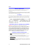
2E4X-27R Overview RESET Button PWR TX RX TX RX RX 18 17 Port Status LEDs TX RX 19 TX RX 20 TX RX 21 TX RX TX RX 22 23 Optional HSIM Slot TX 24 RESET COM CPU RX TX RX 9 TX RX 10 RX TX RX 1 11 TX RX 12 TX RX 13 TX RX TX RX 3 2 TX RX TX RX 14 TX RX 15 TX RX TX RX 5 4 TX RX TX RX 6 7 TX 16 TX 8 2E48-27R 25 System LEDs COM Port 2E48-27R RESET Button PWR 18 17 Port Status LEDs TX RX TX RX RX TX RX 19 26 Network Ports 1 - 24 (ST connectors), Optional Fast
Chapter 1: Introduction 1.3.1 Connectivity The 2E48-27R connects to Ethernet networks or workstations through 24 ST fiber optic ports on the front panel. These ports support multimode fiber optic cables at lengths up to 2 kilometers. The ports are IEEE 802.3 10BASE-F compliant. The 2E49-27R connects to Ethernet networks or workstations through 24 ST fiber optic ports on the front panel. These ports support single mode fiber optic cables at lengths up to 5 kilometers. The ports are FOIRL compliant.
2E4X-27R Overview For more information about SmartTrunk, refer to the Cabletron Systems SmartTrunk User’s Guide. 1.3.4 Runtime IP Address Discovery This feature enables the 2E4X-27R to automatically accept an IP address from a Boot Strap Protocol (BootP) server on the network into NVRAM without requiring a user to enter an IP address through Local Management. When the 2E4X-27R is connected to the network and powered up, Runtime IP Address Discovery (RAD) checks the 2E4X-27R for an IP address.
Chapter 1: Introduction 1.3.6 Switching Options The 2E4X-27R provides IEEE 802.1D switching, IEEE 802.1Q switching, or SecureFast Switching Virtual Network Services between all of the front panel interfaces including Fast Ethernet Interface Modules and High Speed Interface Modules (HSIMs). 802.1Q switching and SecureFast switching allow for future migration to Virtual Network technologies without requiring the replacement of existing equipment. 1.3.
2E4X-27R Overview 1.3.10 Optional Features Options for the 2E4X-27R are Fast Ethernet Interface Modules and High Speed Interface Modules, which add remote uplink capability. Cabletron Systems provides Fast Ethernet Interface Modules to support uplinks to 100 Mbps Ethernet backbones or high speed connections to local servers. Table 1-1 provides a list of the Fast Ethernet Interface Modules. .
Chapter 1: Introduction 1.4 DOCUMENT CONVENTIONS The following conventions are used throughout this document: NOTE TIP ! Note symbol. Calls the reader’s attention to any item of information that may be of special importance. Tip symbol. Conveys helpful hints concerning procedures or actions. Caution symbol. Contains information essential to avoid damage to the equipment. CAUTION Electrical Hazard Warning symbol.
Getting Help 1.5 GETTING HELP For additional support related to this device or document, contact the Cabletron Systems Global Call Center: World Wide Web http://www.cabletron.com/ Phone (603) 332-9400 Internet mail support@cabletron.com FTP ftp://ftp.cabletron.com/ anonymous your email address Login Password To send comments or suggestions concerning this document, contact the Cabletron Systems Technical Writing Department via the following email address: TechWriting@cabletron.
Chapter 1: Introduction 1.
CHAPTER 2 NETWORK REQUIREMENTS Before installing the 2E4X-27R or Fast Ethernet Interface Module (FE-100TX, FE-100FX, or FE-100F3), review the requirements and specifications referred to in this chapter concerning the following: • SmartTrunk (Section 2.1) • 10BASE-F Fiber Optic Network (Section 2.2) • FOIRL Fiber Optic Network (Section 2.3) • 100BASE-TX Twisted Pair Network (Section 2.4) • 100BASE-FX Fiber Optic Network (Section 2.
Chapter 2: Network Requirements 2.3 FOIRL FIBER OPTIC NETWORK When connecting an FOIRL segment to any of the 2E49-27R ports (Interfaces 1 through 24), ensure that the network meets the Ethernet network requirements for FOIRL. Refer to the Cabletron Systems Cabling Guide for details. 2.4 100BASE-TX NETWORK The 2E4X-27R, with an FE-100TX installed in ports 25 and 26, provides an RJ45 connection that supports UTP cabling, which has an impedance of 85 to 111 ohms.
CHAPTER 3 INSTALLATION Only qualified personnel should install the 2E4X-27R. This chapter provides all instructions required to install the 2E4X-27R. A Phillips screwdriver is required to install options into the device or install the device into a rack. Follow the order of the sections listed below to correctly install the 2E4X-27R. • Unpacking the 2E4X-27R (Section 3.1) • Installing Options (Section 3.2) • Installing the 2E4X-27R (on a shelf or tabletop, or into a standard rack) (Section 3.
Chapter 3: Installation 2. Verify the contents of the carton as listed in Table 3-1. Table 3-1 Contents of 2E4X-27R Carton Item Quantity 2E4X-27R 1 Antistatic wrist strap 1 Console Cable Kit 1 Rackmount Kit 1 Strain-Relief Bracket 1 Manual Accessory Kit 1 Power Cord (2E48-27R or 2E49-27R) 2 3. Remove the black and amber tape seal on the non-conductive bag to remove the 2E4X-27R. 4.
Installing the Device 3.3 INSTALLING THE DEVICE The 2E4X-27R may be installed on a tabletop, shelf, or in a 19-inch rack. Section 3.3.1 describes a tabletop or shelf installation and Section 3.3.2 describes the rackmount installation. To prevent possible personal injury and/or damage to the unit, do NOT connect power to the 2E4X-27R until instructed to do so. 3.3.1 Tabletop or Shelf Installation The following two subsections provide guidelines for installation on a tabletop or shelf.
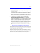
Chapter 3: Installation C B PWR TX RX TX RX RX 18 17 TX RX 19 TX RX 20 TX RX 21 TX RX TX RX 22 23 TX 24 RESET COM CPU RX TX RX 9 A RX TX RX 10 TX RX 1 TX RX TX RX 11 TX RX 2 12 TX RX 13 TX RX TX RX 3 4 TX RX TX RX 14 TX RX 5 15 TX RX TX RX 6 7 TX 16 TX 8 2E48-27R 25 26 D A = 15 cm (6 in) B = 45 cm (22.5 in) C = 53 cm (21 in) D = 213 cm (84 in) 23142-06 Figure 3-1 3.3.
Installing the Device Installation Rack mounting the 2E4X-27R involves the following: • Attaching the strain-relief bracket • Rack mounting the 2E4X-27R (attaching the mounting brackets and fastening the 2E4X-27R to the rack) Attaching the Strain-Relief Bracket Attach the strain-relief bracket to the front of the 2E4X-27R as follows: 1. Locate the strain-relief bracket and four 8-32 x 3/8-inch pan-head screws in the rackmount kit.
Chapter 3: Installation Rack Mounting the 2E4X-27R Proceed as follows to install the 2E4X-27R into a 19-inch rack: 1. Remove and discard the four cover screws (two from each side) located along the front edges of each side of the 2E4X-27R. 2. Locate the four 6-32 x 3/8-inch flathead cover replacement screws in the rackmount kit. Use these screws to attach the rackmount brackets to the 2E4X-27R as shown in Figure 3-3.
Installing the Device 3.3.3 NOTE Connecting Power to the 2E4X-27R The 2E4X-27R has two power supplies with automatic voltage sensing that allows connection to power sources ranging from 100–125 Vac or 200–250 Vac, 50/60 Hz. To connect the 2E4X-27R to the power sources, proceed as follows: 1. Plug each power cord into a grounded wall outlet, see Figure 3-5. To take advantage of the load sharing and redundancy capabilities, each power cord must be plugged into a dedicated ac outlet.
Chapter 3: Installation 3.4 CONNECTING TO THE NETWORK This section provides the procedures for connecting unshielded twisted pair (UTP) and fiber optic segments from the network or other devices to the 2E4X-27R. NOTE If the 2E4X-27R is being installed in a network using SmartTrunking, there are rules concerning the network cable and port configurations that must be followed for SmartTrunking to operate properly.
Connecting to the Network 3.4.1 Connecting Fiber Optic Cables to Ports 1 Through 24 Each fiber optic link consists of two strands of fiber optic cabling: the transmit (TX) and the receive (RX). The transmit strand from a 2E4X-27R port connects to the receive port of a fiber optic Ethernet device at the other end of the segment. The receive strand of the applicable port on the 2E4X-27R connects to the transmit port of the fiber optic Ethernet device.
Chapter 3: Installation 4. At the other end of the fiber optic cable, attach the fiber pair to the transmit and receive ports of the device. . Receive (RX) LED RX TX 23141-07 Figure 3-6 Fiber Optic Connection 5. Verify that a link exists by checking that the port RX LED is on (flashing amber, blinking green, or solid green). If the RX LED is off, perform the following steps until it is on: a. Verify that the device at the other end of the segment is ON and connected to the segment. b.
Connecting to the Network An FE-100TX installed in port slot 25 and/or 26 has an internal crossover switch. When connecting a workstation, use a straight-through cable and set the Fast Ethernet Interface Module crossover switch shown in Figure 3-7 to the crossed over position marked with X.
Chapter 3: Installation 2. Connect the twisted pair segment to the module by inserting the RJ45 connector on the twisted pair segment into the RJ45 port on the module shown in Figure 3-7. 3. Verify that a link exists by checking that the port RX LED is on (flashing amber, blinking green, or solid green). If the RX LED is off and the TX LED is not blinking amber, perform the following steps until it is on: a. Verify that the 100BASE-TX device at the other end of the twisted pair segment is powered up. b.
Connecting to the Network Fiber Optic Network Connection 1. Remove the protective plastic covers from the fiber optic ports on the applicable port on the module and from the ends of the connectors. ! CAUTION ! CAUTION The FE-100F3 uses Class 1 lasers. Do not use optical instruments to view the laser output. The use of optical instruments to view laser output increases eye hazard. When viewing the output optical port, power must be removed from the network adapter.
Chapter 3: Installation 4. Verify that a link exists by checking that the port RX LED is ON (flashing amber, blinking green, or solid green). If the RX LED is OFF and the TX LED is not blinking amber, perform the following steps until it is on: The port RX LED flashes green and amber during bootup. NOTE a. Check that the power is turned on for the device at the other end of the link. b.
CHAPTER 4 TROUBLESHOOTING This chapter provides information concerning the following: • Using LANVIEW (Section 4.1) • FE-100TX LED (Section 4.2) • Troubleshooting Checklist (Section 4.3) • Using the RESET Button (Section 4.4) 4.1 USING LANVIEW The 2E4X-27R uses the Cabletron Systems built-in visual diagnostic and status monitoring system called LANVIEW. The LANVIEW LEDs (Figure 4-1) allow quick observation of the network status to aid in diagnosing network problems.
Chapter 4: Troubleshooting NOTE The terms flashing, blinking, and solid used in the following tables indicate the following: Flashing indicates an LED is flashing randomly. Blinking indicates an LED is flashing at a steady rate (approximately 50% on, 50% off). Solid indicates a steady LED light. No pulsing. Table 4-1 LANVIEW LEDs LED Color State Recommended Action PWR OFF Device electronics not receiving power from power supply(ies). 1.
Using LANVIEW Table 4-1 LANVIEW LEDs (Continued) LED Color State Recommended Action RX (Receive) Off No link. No activity. Port enabled or disabled. No error. Green Solid. Port enabled, link, no activity. No error. Blinking. Port disabled, link. No error. Amber Flashing. Port enabled, link, activity. No error. Red Diagnostic failure. Contact the Cabletron Systems GCC for assistance. Off Port enabled, and no activity.
Chapter 4: Troubleshooting 4.2 FE-100TX LED The optional FE-100TX has one LED labeled 10/100. The 10/100 LED together with the receive LED allows the user to determine the link status and the operating speed of the Fast Ethernet Interface Module. The 10/100 LED and the Receive (RX) LED are shown in Figure 4-2. Table 4-2 and Table 4-3 provide a functional description of the 10/100 LED when the RX LED is on or off, respectively.
FE-100TX LED NOTE No link exists if the associated port (25 or 26) RX (Receive) LED is off. Table 4-3 10/100 LED Indications When RX LED Is Off LED Color Indication 10/100 Off No link or no cable attached. FE-100TX forced to 10 Mbps operation, or is manually set to “auto-negotiate” mode. Green No link or no cable attached. FE-100TX is forced to 100 Mbps operation.
Chapter 4: Troubleshooting 4.3 TROUBLESHOOTING CHECKLIST If the 2E4X-27R is not working properly, refer to Table 4-4 for a checklist of possible problems, causes, and recommended actions to resolve the problem. Table 4-4 Troubleshooting Checklist Problem Possible Cause Recommended Action All LEDs are OFF. Loss of power. Check for proper connection of the power cable and its access to a live outlet. Installed improperly. Check the installation.
Using the RESET Button 4.4 USING THE RESET BUTTON The RESET button shown in Figure 4-3 resets the 2E4X-27R processor without affecting the NVRAM. ! CAUTION Pressing the RESET button resets the device, and all current switching being performed by the device is halted. A network downtime of up to two minutes will result from this action.
Chapter 4: Troubleshooting 4-8 2E48-27R/2E49-27R User’s Guide
CHAPTER 5 LOCAL MANAGEMENT This chapter explains how to set up a management terminal to access Local Management. It also explains how to use the Local Management screens and commands. 5.1 OVERVIEW Local Management for the 2E4X-27R consists of a series of screens that allow the management of the 2E4X-27R. The screens allow the user to do the following tasks: • Assign IP address and subnet mask. • Select a default gateway. • Control access by establishing community names.
Chapter 5: Local Management 5.2 LOCAL MANAGEMENT KEYBOARD CONVENTIONS All key names appear as capital letters in this manual. Table 5-1 explains the keyboard conventions and the key functions that are used. Table 5-1 Keyboard Conventions Key Function ENTER Key RETURN Key These are selection keys that perform the same Local Management function. For example, “Press ENTER” means that you can press either ENTER or RETURN, unless this manual specifically instructs you otherwise.
Management Terminal Setup 5.
Chapter 5: Local Management 5.3.1 Console Cable Connection Use the Console Cable Kit provided with the 2E4X-27R to attach the management terminal to the 2E4X-27R COM port as shown in Figure 5-1. Connect an IBM PC or compatible device, running the VT terminal emulation, to the 2E4X-27R as follows: 1. Connect the RJ45 connector at one end of the cable (supplied in the kit) to the COM port on the 2E4X-27R. 2.
Management Terminal Setup 5.3.2 Management Terminal Setup Parameters Table 5-2 lists the setup parameters for the local management terminal.
Chapter 5: Local Management 5.3.3 Telnet Connections Once the 2E4X-27R has a valid IP address, the user can establish a Telnet session with Local Management from any TCP/IP based node on the network. Telnet connections to the 2E4X-27R require the community name passwords assigned at the SNMP Community Names screen of the 2E4X-27R. For information about setting the IP address, refer to Section 5.7. For information about assigning community names, refer to Section 5.8.
Management Terminal Setup 5.3.4 Monitoring an Uninterruptible Power Supply If the 2E4X-27R is connected to an American Power Conversion (APC) Uninterruptible Power Supply (UPS) device for protection against the loss of power, a connection from the 2E4X-27R COM port to the UPS can be made to monitor the power status of the UPS. To use the COM port for this purpose, it must be reconfigured to support the UPS connection using the procedure described in Section 5.7.10, Configuring the COM Port.
Chapter 5: Local Management 5.4 ACCESSING LOCAL MANAGEMENT Access to Local Management is controlled through the Local Management Password screen shown in Figure 5-3. Whenever a connection is made to the 2E4X-27R the Local Management Password screen displays. Before continuing, the user must enter a password (community name) which is compared to the previously stored passwords. The level of access allowed the user depends on the password. To set or change passwords, refer to Section 5.8.
Accessing Local Management NOTE The User’s password is one of the community names specified in the SNMP Community Names screen. Access to certain Local Management capabilities depends on the degree of access accorded that community name. Refer to Section 5.8. If an invalid password is entered, the terminal beeps and the cursor returns to the beginning of the password entry field.
Chapter 5: Local Management \ Device Configuration Menu Password Device Menu General Configuration SNMP Community Names SNMP Traps Switch Configuration Ethernet Full Duplex Configuration SmartTrunk Configuration Device Specific Configuration Menu Device Statistics Menu Switch Statistics Interface Statistics RMON Statistics Network Tools System Resources High Speed Interface Configuration Flash Download Port Redirect Function Broadcast Suppression Fast Ethernet Interfaces HSIM 23142-43 Figure 5-4
Accessing Local Management Device Configuration Menu General Configuration SNMP Community Names SNMP Traps Ethernet Full Duplex Configuration Password Device Menu Device Specific Configuration Menu Device Statistics Menu Interface Statistics RMON Statistics System Resources High Speed Interface Configuration Flash Download Fast Ethernet Interfaces HSIM Port Redirect Function Network Tools Figure 5-6 5.4.
Chapter 5: Local Management Using the RETURN Command To exit LM using the RETURN command, proceed as follows: 1. Use the arrow keys to highlight the RETURN command at the bottom of the Local Management screen. 2. Press ENTER. The previous screen in the Local Management hierarchy displays. NOTE The user can also exit Local Management screens by pressing ESC twice. This exit method does not warn about unsaved changes and all unsaved changes are lost. 3.
Device Menu Screen 5.5 DEVICE MENU SCREEN The Device Menu screen is the access point for all Local Management screens. Figure 5-7 shows the Device Menu screen. 2E48-27R LOCAL MANAGEMENT Device Menu Device Type: 2E48-27R Firmware Revision: XX.XX.XX BOOTPROM Revision: XX.XX.XX DEVICE CONFIGURATION DEVICE STATISTICS NETWORK TOOLS EXIT RETURN 23142-13 Figure 5-7 NOTE Device Menu Screen If the terminal is idle for several minutes, the Local Management Password screen redisplays and the session ends.
Chapter 5: Local Management For details about the Device Configuration Menu screen, refer to Section 5.6. For details about the Device Specific Configuration Menu screen, refer to Section 5.12. DEVICE STATISTICS Device Statistics accesses the Device Menu screen, which provides access to screens that allow the user to obtain switch, interface, and RMON statistics information about the 2E4X-27R. For details, refer to Section 5.19.
Device Configuration Menu Screen To access the Device Configuration Menu screen from the Device Menu screen, use the arrow keys to highlight the DEVICE CONFIGURATION menu item and press ENTER. The Device Configuration Menu screen displays. 2E48-27R LOCAL MANAGEMENT Device Configuration Menu Device Type: 2E48-27R Firmware Revision: XX.XX.XX BOOTPROM Revision: XX.XX.
Chapter 5: Local Management SNMP TRAPS The SNMP Traps screen provides display and configuration access to the table of IP addresses used for trap destinations and associated community names. For details, refer to Section 5.9. SWITCH CONFIGURATION The Switch Configuration screen provides the basic setup options for customizing the operation of a switch device in the network. For details, refer to Section 5.10.
General Configuration Screen 5.7 GENERAL CONFIGURATION SCREEN The General Configuration screen, Figure 5-9, allows the user to set the system date and time, IP address and subnet mask, the default gateway, the TFTP gateway IP address, and the operational mode. Also, clear the NVRAM, set the screen refresh time, the screen lockout time, the IP fragmentation, the COM port configuration, and monitor the total time (uptime) that the device has been running.
Chapter 5: Local Management IP Address (Modifiable) Displays and allows the user to set the IP address for the 2E4X-27R. To set the IP address, refer to Section 5.7.1. The IP address can also be set through Runtime IP Address Discovery as previously described in Section 1.3.4. Subnet Mask (Modifiable) Displays the subnet mask for the 2E4X-27R.
General Configuration Screen Screen Lockout Time (Modifiable) Contains the maximum number of minutes that the Local Management application displays a device’s screen while awaiting input or action from a user. For example, if the number 5 is entered in this field, the user has up to five minutes to respond to each of the specified device’s Local Management screens.
Chapter 5: Local Management Application (Toggle) Allows the user to set the application that the COM port will support. The field toggles between LM (Local Management) and UPS (Uninterruptible Power Supply). The default is LM. The UPS setting allows the COM port to be used to monitor an American Power Conversion (APC) Uninterruptible Power Supply (UPS). The baud rate setting for LM is automatically sensed. For UPS, the baud rate is automatically set to 2400.
General Configuration Screen 4. Use the arrow keys to highlight the SAVE command, then press ENTER. The warning screen shown in Figure 5-11 displays. WARNING! YOU HAVE ELECTED TO SAVE ONE OR MORE CONFIGURATION ITEMS THAT REQUIRE RESETTING THIS MODULE. ARE YOU SURE YOU WANT TO CONTINUE? NO YES 19601-84 Figure 5-10 Configuration Warning Screen 5. Use the arrow keys to highlight the YES command, then press ENTER. The changes are saved and the device reboots. 5.7.
Chapter 5: Local Management 3. Press ENTER. If the subnet mask is valid, the cursor returns to the beginning of the Subnet Mask field. If the entry is not valid, the screen displays the message “INVALID SUBNET MASK OR FORMAT ENTERED”. Local Management does not alter the current value, but it does refresh the Subnet Mask field with the previous value. 4. Use the arrow keys to highlight the SAVE command, then press ENTER. The warning screen shown in Figure 5-11 displays.
General Configuration Screen 5.7.3 Setting the Default Gateway If the SNMP management station is located on a different IP subnet than the 2E4X-27R, a default gateway must be specified. When an SNMP Trap is generated, the 2E4X-27R sends the Trap to the default gateway. To set the default gateway, perform the following steps: 1. Use the arrow keys to highlight the Default Gateway field. 2. Enter the IP address of the default gateway using the DDN format. For example: 134.141.79.121 3. Press ENTER.
Chapter 5: Local Management WARNING! YOU HAVE ELECTED TO SAVE ONE OR MORE CONFIGURATION ITEMS THAT REQUIRE RESETTING THIS MODULE. ARE YOU SURE YOU WANT TO CONTINUE? NO YES 19601-84 Figure 5-12 Configuration Warning Screen 5. Use the arrow keys to highlight the YES command, then press ENTER. The changes are saved and the device reboots. 5.7.5 Setting the Device Date The 2E4X-27R is year 2000 compliant so that the Device Date field can be set beyond the year 1999.
General Configuration Screen 4. Use the arrow keys to highlight the SAVE command at the bottom of the screen and press ENTER. If the date entered is a valid format, the message displays “SAVED OK” at the top of the screen. If the entry is not valid, Local Management does not alter the current value, but it does refresh the Device Date field with the previous value. 5.7.6 Setting the Device Time To set the device time, perform the following steps: 1. Use the arrow keys to highlight the Device Time field.
Chapter 5: Local Management 4. Use the arrow keys to highlight the SAVE command at the bottom of the screen and press ENTER. If the time entered is within the 3 to 99 seconds range, the message “SAVED OK” displays at the top of the screen. If the entry is not valid, Local Management does not alter the current setting, but it does refresh the Screen Refresh Time field with the previous value. 5.7.
General Configuration Screen WARNING! YOU HAVE ELECTED TO SAVE ONE OR MORE CONFIGURATION ITEMS THAT REQUIRE RESETTING THIS MODULE. ARE YOU SURE YOU WANT TO CONTINUE? NO YES 19601-84 Figure 5-13 Configuration Warning Screen 4. Use the arrow keys to highlight the YES command, then press ENTER. The changes are saved and the device reboots. Upon saving the new operational mode, the module will reboot. NOTE If the 2E4X-27R is set to 802.
Chapter 5: Local Management 5.7.10 Configuring the COM Port Upon power up, the COM port is configured to the default settings of ENABLED and LM. ! CAUTION Before altering the COM port settings, ensure that the 2E4X-27R is set with a valid IP address. (Refer to Section 5.7.1, Setting the IP Address.) Read this entire COM port configuration section before changing the settings of the COM port.
General Configuration Screen WARNING THE COM PORT HAS BEEN RECONFIGURED AND THERE IS NO IP ADDRESS SET FOR THIS DEVICE. YOU WILL NO LONGER BE ABLE TO MANAGE THIS BOARD. DO YOU STILL WISH TO RECONFIGURE THIS COM PORT? NO YES 174252 Figure 5-14 COM Port Warning Screen 3. Use the arrow keys to highlight YES. Press ENTER. 4. If the port was ENABLED, the message “SAVED OK” appears, and the edits are saved.
Chapter 5: Local Management 5.7.10.1 Changing the Com Port Application After enabling the COM port as described in Section 5.7.10, one of the applications supported by the COM port (LM or UPS) can be selected. The default application is LM. To change the COM port application: 1. Use the arrows keys to highlight the Application field. 2. Use the SPACE bar or BACKSPACE to step through the available settings until the operation you require appears.
General Configuration Screen 5.7.11 Clearing NVRAM ! CAUTION Clearing NVRAM results in the loss of all user-entered parameters. Do not proceed unless the following procedure is completely understood. Clearing NVRAM allows the user to clear all user-entered parameters, such as the IP address and Community Names from NVRAM. Clear NVRAM as follows: 1. Use the arrow keys to highlight the Clear NVRAM field. 2. Use the SPACE bar to toggle the field to YES. 3.
Chapter 5: Local Management 5.7.12 Enabling/Disabling IP Fragmentation To enable or disable IP Fragmentation, proceed as follows: ! CAUTION If the 2E4X-27R is being bridged to an FDDI ring (for example, via an optional HSIM-F6), IP Fragmentation should be enabled. If it is disabled, all FDDI frames that exceed the maximum Ethernet frame size are discarded. 1. Use the arrow keys to highlight the IP Fragmentation field. 2. Press the SPACE bar to choose either ENABLED or DISABLED. 3.
SNMP Community Names Screen 5.8 SNMP COMMUNITY NAMES SCREEN The SNMP Community Names screen allows the user to set SNMP Management community names. Community names act as passwords to Local/Remote Management and are agents of security access to the 2E4X-27R. Access to the 2E4X-27R is controlled by enacting any of three different levels of security authorization (read-only, read-write, and super-user).
Chapter 5: Local Management The following explains each SNMP Community Names screen field: Community Name (Modifiable) Displays the user-defined name through which a user accesses the 2E4X-27R SNMP Management. Any community name assigned here acts as a password to Local/Remote Management. Access Policy (Read-Only) Indicates the access accorded each community name.
SNMP Community Names Screen 5.8.1 Establishing Community Names The password used to access Local Management at the Password Screen must have super-user access to view and edit the SNMP Community Names screen. Using a password with read-only or read-write access does not allow the user to view or edit the SNMP Community Names screen. NOTE Any community name assigned in the SNMP Community Names screen is a password to its corresponding level of access to Local/Remote Management.
Chapter 5: Local Management 5.9 SNMP TRAPS SCREEN Since the 2E4X-27R is an SNMP compliant device, it can send messages to multiple Network Management Stations to alert users of status changes. The SNMP Traps screen is shown in Figure 5-17. To access the SNMP Traps screen from the Device Configuration Menu screen, use the arrow keys to highlight the SNMP TRAPS menu item and press ENTER. The SNMP Traps screen displays.
SNMP Traps Screen Enable Traps (Toggle) Enables transmission of the traps to the network management station with the associated IP address. This field toggles between YES and NO. 5.9.1 Configuring the Trap Table To configure the Trap table, proceed as follows: 1. Use the arrow keys to highlight the appropriate Trap Destination field. 2. Enter the IP address of the workstation that is to receive traps. IP address entries must follow the DDN format. For example: 134.141.79.121 3. Press ENTER.
Chapter 5: Local Management 5.10 SWITCH CONFIGURATION SCREEN The Switch Configuration screen, Figure 5-18, provides the basic setup options to make a switch operational in your network. The Switch Configuration screen is not available if the operational mode of the device is set to SECURE FAST VLAN. This screen may only be used when the device is configured to operate as an 802.1D or 802.1Q switch.
Switch Configuration Screen The following describes each field of the Switch Configuration screen: Switch Address (Read-Only) Displays the base MAC address of the switch. Number of Ports (Read-Only) Displays the total number of switched ports on the 2E4X-27R. Depending on the optional interfaces, there can be 24 through 27.
Chapter 5: Local Management Learning: The switch is learning the addresses on this interface. The switch enters the learning state when the Transparent Database is created (during start-up or after being deleted), or when the Spanning Tree Algorithm detects a network topology change. Forwarding: The switch is operating and this interface is forwarding traffic. Standby: This interface will not forward any traffic through the switch because a loop condition has been detected by the STA.
Switch Configuration Screen 5.10.2 Setting the Age Time Field To set the Age Time, proceed as follows: 1. Use the arrow keys to highlight the Age Time field. 2. Type in the desired Age Time in increments of 10. The available Age Time range is 10 to 1,000,000 seconds with the default value being 300 seconds. 3. Use the arrow keys to highlight the SAVE command at the bottom of the screen. 4. Press ENTER. The message “SAVED OK” is displays. 5.10.
Chapter 5: Local Management 5.11 ETHERNET FULL DUPLEX CONFIGURATION SCREEN The Ethernet Full Duplex Configuration screen, Figure 5-19, allows the user to set ports 1 through 24, individually or all at once, to either Standard Ethernet or Full Duplex operation, and monitor each port to see whether or not it is enabled and linked to another 10BASE-F device. Refer to Section 5.15 to set the Operation Mode for ports 25 and 26.
Ethernet Full Duplex Configuration Screen OPERATION MODE (Toggle) Allows the user to set the specified port to transmit and receive data separately (Standard) or simultaneously (Full Duplex). Set this field to one of the following values: • STANDARD ENET – The port is running at 10 Mbps (default) and either transmits data or receives data, but not both at the same time. To set Ethernet ports for Standard operation, refer to Section 5.11.1.
Chapter 5: Local Management [1-12] or [13-24] (Navigation Key) When the Full Duplex Configuration screen displays, the current operation mode and status information are displayed for the first 12 ports. This field allows the user to step to the second screen for the same type of information for ports 13 through 24. While on the second screen, the user can navigate back to the first screen by highlighting the [1-12] field and pressing ENTER.
Device Specific Configuration Menu Screen 5.12 DEVICE SPECIFIC CONFIGURATION MENU SCREEN The Device Specific Configuration Menu screen, Figure 5-20, allows the user to select one of five screens to configure ports or check system resources specific to the 2E4X-27R.
Chapter 5: Local Management The following briefly defines each selectable item of the Device Specific Configuration Menu screen: SYSTEM RESOURCES The System Resources screen displays the amount of FLASH memory, DRAM and NVRAM installed, indicates the amount of available memory and provides information on 2E4X-27R operation. For details, refer to Section 5.13.
System Resources Screen 5.13 SYSTEM RESOURCES SCREEN The System Resources screen, Figure 5-21, provides information concerning the processor used in the 2E4X-27R and the amount of FLASH memory, DRAM, and NVRAM that is installed and how much of that memory is available. This screen also allows the user to monitor the current processor (switch) utilization and the peak switch utilization.
Chapter 5: Local Management Flash Memory Installed (Read-only) Indicates the amount of FLASH memory installed in the 2E4X-27R and how much is currently available. DRAM Installed (Read-only) Indicates the amount of DRAM installed in the 2E4X-27R and how much of it is currently available. NVRAM Installed (Read-only) Indicates the amount of NVRAM installed in the 2E4X-27R and how much of it is currently available.
High Speed Interface Configuration Menu Screen 5.14 HIGH SPEED INTERFACE CONFIGURATION MENU SCREEN The High Speed Interface Configuration Menu screen, Figure 5-22, applies to the Fast Ethernet Interface Modules and the High Speed Interface Module. NOTE This screen does not display unless one or two Fast Ethernet Interface Modules and a High Speed Interface Module (HSIM) are installed.
Chapter 5: Local Management The following briefly explains each screen accessible from the High Speed Interface Configuration Menu screen. FAST ETHERNET INTERFACES Displays a screen named High Speed Interface Configuration. This screen shows the types of Fast Ethernet Interface Modules installed in ports 25 and 26, their current operating mode, and indicates if the ports are linked. This screen also allows the user to enable or disable Auto-Negotiation and set the Advertised Ability.
High Speed Interface Configuration Screen Event Message Line 2E48-27R LOCAL MANAGEMENT High Speed Interface Configuration Device Type: 2E48-27R Firmware Revision: XX.XX.XX BOOTPROM Revision: XX.XX.XX Port 25 Port 26 Port Type FE-100TX Unknown Link Status Link N/A Current Oper. Mode 100Base-TXFD [N/A] Desired Oper.
Chapter 5: Local Management Current Oper. Mode (Read-only) This field displays the current operating mode of ports 25 and 26. Depending on whether a 100BASE-FX or 100BASE-TX Fast Ethernet Interface Module is installed, this field displays the following: • With a 100BASE-FX interface: 100Base-FX, 100Base-FXFD (full duplex), or N/A when the port slot is empty.
High Speed Interface Configuration Screen Advertised Ability (Selectable) During auto-negotiation, the FE-100TX informs the device at the other end of the segment about its capabilities. The capabilities of a port (25 or 26) with an FE-100TX installed are 10BASE-T, 10BASE-TFD (full duplex mode), 100BASE-TX and 100BASE-TXFD (full duplex mode). In normal operation, with all capabilities enabled, the FE-100TX “advertises” that it has the ability to operate in any mode.
Chapter 5: Local Management 5.15.2 Configuring an FE-100TX In normal operation, a port (25 or 26) with an FE-100TX interface automatically establishes a link with the device at the other end of the segment and no user setup is required. Section 5.15.2.1 and Section 5.15.2.2 provide instructions for manually configuring the port with an FE-100TX installed. 5.15.2.1 Setting the FE-100TX Operational Mode Use the Desired Oper. Mode field to set the active technology.
FLASH Download Screen 3. Use the LEFT-ARROW key to move back to the Advertised Ability selection and use the SPACE bar to select the next mode to enable or disable. 4. Use the RIGHT-ARROW key to move across to the Enabled/Disabled field to the right of the selection. 5. Use the SPACE bar to select Enabled or Disabled. Press ENTER. Continue this process until you have completed enabling or disabling the advertised modes. 6. Use the arrow keys to highlight the SAVE command. Press ENTER.
Chapter 5: Local Management To access the Flash Download screen from the Device Specific Configuration Menu screen, use the arrow keys to highlight the FLASH DOWNLOAD menu item and press ENTER. The Flash Download screen displays. TFTP DOWNLOAD. WILL COMMIT TO FLASH. REBOOT IN PROGRESS... 2E48-27R LOCAL MANAGEMENT Flash Download Device Type: 2E48-27R Firmware Revision: XX.XX.XX BOOTPROM Revision: XX.XX.XX Download Method: [TFTP] Reboot After Download: [YES] TFTP Gateway IP Addr: 134.141.79.
FLASH Download Screen Section 5.16.2 describes how to download using TFTP. Section 5.16.3 describes how to download using Runtime. Reboot After Download (Modifiable only when RUNTIME is chosen.) This field notifies the user that the 2E4X-27R will reboot after the download is complete. If a Runtime Download is performed, this field toggles between YES and NO. If YES is selected, the device reboots after the download is completed.
Chapter 5: Local Management 5.16.1 Image File Download Using BootP To download a firmware image of FLASH to the 2E4X-27R using BootP, proceed as follows: 1. Use the arrow keys to highlight the Download Method field. 2. Use the SPACE bar to select BOOTP. 3. Use the arrow keys to highlight the TFTP Gateway IP Addr field. 4. Set the IP address of the TFTP gateway server (this defaults to the same IP address set in the TFTP Gateway IP Addr field in the General Configuration screen). 5.
FLASH Download Screen 9. Use the arrow keys to highlight EXECUTE at the bottom of the screen and press ENTER. The message “TFTP DOWNLOAD. WILL COMMIT TO FLASH. REBOOT IN PROGRESS...” displays in the event message line at the top of the screen and the new image is downloaded into FLASH memory. 5.16.3 Image File Download Using Runtime To download a firmware image of FLASH to the 2E4X-27R using Runtime, proceed as follows: 1. Use the arrow keys to highlight the Download Method field. 2.
Chapter 5: Local Management 5.17 NOTE PORT REDIRECT FUNCTION SCREEN The Port Redirect Function screen may not be available depending on the operational mode setting of the device. Refer to the Release Notes to see which operational modes support the Port Redirect Function screen. Section 5.7.9 describes how to configure the device to operate in this mode. The Port Redirect Function screen, Figure 5-25, allows the user to set each port (1 through 26) as a source or destination port.
Port Redirect Function Screen Event Message Line 2E48-27R LOCAL MANAGEMENT Port Redirect Function Device Type: 2E48-27R Firmware Revision: XX.XX.XX BOOTPROM Revision: XX.XX.
Chapter 5: Local Management Destination Port [n] (Selectable) Allows a selected port [n] to be changed to a destination port. For details, refer to Section 5.17.2. Errors (Toggle) Allows the user to configure the source ports to either ON to send errored frames to selected destination ports, or OFF to drop errored frames, and send only valid traffic to the destination ports. The default setting of this field is ON.
Port Redirect Function Screen 5.17.2 Changing Source and Destination Ports Add or delete source port and destination port entries as follows: 1. Use the arrow keys to highlight the Source Port field. 2. Press the SPACE bar or BACKSPACE one or more times to increment or decrement the port number displayed in the brackets [n] until the appropriate port number displays. 3. Use the arrow keys to highlight the Destination Port field. 4.
Chapter 5: Local Management 5.18 BROADCAST SUPPRESSION SCREEN The Broadcast Suppression screen, Figure 5-26, allows the user to set a desired limit of receive broadcast frames that are switched out to the other ports. The Broadcast Suppression screen may not be available if the operational mode of the device is set to SECURE FAST VLAN. Refer to the Release Notes to see which operational modes support the Broadcast Suppression screen. Section 5.7.
Broadcast Suppression Screen The following explains each field of the Broadcast Suppression screen: PORT # (Read-only) Identifies the number of the port. Total RX (Read-Only) Displays the total number of broadcast frames received. Peak Rate (Read-Only) Displays the highest number of broadcast frames received in a one second interval. Time Since Peak (Read-Only) Displays the time since peak rate was achieved.
Chapter 5: Local Management 3. Use the arrow keys to highlight the SAVE command at the bottom of the screen. 4. Press ENTER. The message “SAVED OK” displays. 5.18.2 Setting the Reset Peak To set the Reset Peak field to YES or NO, proceed as follows: 1. Use the arrow keys to highlight the Reset Peak field for the selected port. 2. Press the SPACE bar to select YES or NO. 3. Use the arrows keys to highlight the SAVE command at the bottom of the screen. 4. Press ENTER.
Device Statistics Menu Screen 2E48-27R LOCAL MANAGEMENT Device Statistics Menu Device Type: 2E48-27R Firmware Revision: XX.XX.XX BOOTPROM Revision: XX.XX.XX SWITCH STATISTICS INTERFACE STATISTICS RMON STATISTICS EXIT RETURN 23142-67 Figure 5-27 Device Statistics Menu Screen The Device Statistics Menu screen displays the following menu items: SWITCH STATISTICS The Switch Statistics screen lists the number of frames received, transmitted, filtered, and forwarded by each interface.
Chapter 5: Local Management 5.20 SWITCH STATISTICS SCREEN The Switch Statistics screen, Figure 5-28, lists the number of frames received, transmitted, filtered, and forwarded by each interface. NOTE The Switch Statistics screen is not available if the operational mode of the device is set to SECURE FAST VLAN. Section 5.7.9 describes how to set the operational mode.
Switch Statistics Screen Frames Rcvd (Read-Only) Displays the number of frames received by the interface since last power-up or reset. Frames Txmtd (Read-Only) Displays the number of frames transmitted by the interface since last power-up or reset. Frames Fltrd (Read-Only) Displays the number of frames filtered by the interface since last power-up or reset. Frames Frwded (Read-Only) Displays the number of frames forwarded by the interface.
Chapter 5: Local Management 5.21 INTERFACE STATISTICS SCREEN The Interface Statistics screen, Figure 5-29, is used to gather MIB-II statistics for the 2E4X-27R interfaces (ports 1 through 26) with the exception of an installed HSIM. Cabletron Systems HSIMs gather their own statistics, and may be viewed via the Local Management screens of the applicable HSIM. Refer to your HSIM documentation for information on how to access these screens.
Interface Statistics Screen The following definitions explain each field of the Interface Statistics screen: Interface (Read-Only) This field displays the Interface number for which statistics are currently being displayed. Figure 5-29 shows the Interface field displaying 1. This represents Port 1 of the device. To view other interface statistics, refer to Section 5.21.1. Name (Read-Only) The Name field displays the type of interface for which statistics are being displayed.
Chapter 5: Local Management InUnknownProtos (Read-Only) The InUnknownProtos field displays the total number of frames that were discarded because the frames were in an unknown or unsupported format. OutOctets (Read-Only) This field displays the total number of octets (bytes) that have been transmitted from the Interface. OutUnicast (Read-Only) The OutUnicast field displays the total number of frames transmitted that were sent to a single address.
Interface Statistics Screen Oper Status (Read-Only) This field displays the current status of the interface. If this field displays “Testing”, no frames may be passed on this interface. MTU (Read-Only) The MTU field displays the maximum frame size (in octets) that a frame may contain to be received or transmitted from this interface. Speed (Read-Only) The Speed field displays the theoretical maximum of the interface’s bandwidth in bits per second.
Chapter 5: Local Management 5.21.2 Using the Clear Counters Command To reset all the statistics counters of the selected interface to zero, perform the following steps: 1. Use the arrow keys to highlight the CLEAR COUNTERS command. 2. Press ENTER, the counters for the selected interface are reset to zero. 5.22 RMON STATISTICS SCREEN RMON statistics for each interface, on an interface-by-interface basis, are viewed through the RMON Statistics screen shown in Figure 5-30.
RMON Statistics Screen The following briefly defines each field of the RMON Statistics screen: RMON Index (Read-only) This field displays the current Ethernet interface for which statistics are being shown. The 2E4X-27R has an embedded RMON agent that gathers statistics for each interface on the device. Data Source (Read-only) This field displays the source of the statistics data that is currently being displayed on the screen.
Chapter 5: Local Management Multicasts (Read-only) The Multicast field displays the total number of good frames received that were directed to a multicast address. The value of this field does not include frames directed to the broadcast address. CRC Align Errors (Read-only) This field displays the number of frames with bad Cyclic Redundancy Checks (CRC) received from the network.
RMON Statistics Screen Total Octets (Read-only) This field displays the total number of octets (bytes) of data, including those in bad frames, received on this interface. 64 Octets (Read-only) Displays the total number of frames, including bad frames, received that were 64 bytes in length (excluding framing bits, but including FCS bytes).
Chapter 5: Local Management 5.22.1 Displaying RMON Statistics To display the statistics for any index, proceed as follows: 1. Use the arrow keys to highlight the Index [nn] field at the bottom of the screen. 2. Press the SPACE bar to increment (or press the DEL [delete] key to decrement) the index number. 3. Press ENTER (neither the RMON Index # field nor the statistics will change until ENTER is pressed). 5.22.
Network Tools 5.23 NETWORK TOOLS The Network Tools function allows the user to access and manage network devices. Figure 5-31 shows the Network Tools Help screen. To access the Network Tools screen, use the arrow keys to highlight the NETWORK TOOLS menu item in the Device Menu screen and press ENTER. The Network Tools Help screen displays.
Chapter 5: Local Management There are two categories of commands in the command set. • Built-in Commands – Allow the user to access and manage network devices. The commands are arp, bridge, defroute, netstat, ping, reset, show, traceroute, soft-reset, telnet, link_trap, and atm_stp_state. The atm_stp_state command selection only displays when an HSIM is installed. • Special Commands – Allow the user to exit from Network Tools. The commands are done, exit, and quit.
Network Tools 5.23.1 Built-in Commands The built-in commands listed in this section activate functions on the LM managed device or devices being accessed through Network Tools. arp: Syntax: arp [options] Description: The arp command provides access to the ARP (Address Resolution Protocol) cache, enabling you to view cache data, delete entries, or add a static route. Super-user access is required to delete an entry or add a static route.
Chapter 5: Local Management Example: -> arp -a # Interface # 30 # 30 # 30 # 30 Network Address 122.144.40.111 122.144.48.109 122.144.52.68 122.144.21.43 Physical Address 00.00.0e.12.3c.04 00.00.0e.f3.3d.14 00.00.0e.12.3c.04 00.00.0e.03.1d.3c Media Type 3(dynamic) 3(dynamic) 3(dynamic) 3(dynamic) -> arp -d 1 122.144.52.68 -> arp -s 1 22.44.2.
Network Tools defroute: Syntax: defroute defroute [interface number] [IP address] defroute delete [interface number] [IP address] Description: The defroute command allows the user, in the syntax order shown above, to view, set, or delete the default IP route to a managed device through the specified interface. Options: Not Applicable Example: -> defroute 2 147.152.42.32 # Default route is 147.152.42.32 on interface 2 -> defroute # Default route is 147.152.42.
Chapter 5: Local Management Example: -> netstat -i Interface + Description MTU Speed Admin Oper MAC Addr # 1 (ethernet -csmacd) # 2 (ethernet - csmacd) # 3 (ethernet - csmacd) # 4 (ethernet - csmacd) 1514 1514 1514 1514 10000000 10000000 10000000 10000000 up up up up up up up up 0x00 0x00 0x1d 0x07 0x50 0x0e 0x00 0x00 0x1d 0x07 0x50 0x0f 0x00 0x00 0x1d 0x07 0x50 0x10 0x00 0x00 0x1d 0x07 0x50 0x11 -> netstat -r Destination Next-hop Interface # Default Route # 134.141.0.0 # 134.141.0.
Network Tools NOTE The Network Tools connection to the device will be terminated upon execution of this command. Options: Not Applicable Example: -> reset RESET: Are you *SURE* ? -> Y 17422-45 show: Syntax: show [PROTOCOL]
Description: The show command displays information concerning various components of the device. Protocols currently supported are IP, IPX, DECnet, and AppleTalk.Chapter 5: Local Management traceroute: Syntax: traceroute [IP address] Description: The traceroute command generates a TRACEROUTE request to a specified IP address and provides a display of all next-hop routers in the path to the device. If the device is not reached, the command displays all next-hop routers to the point of failure. Options: Not Applicable Example: -> traceroute 122.144.11.52 # next-hop[0] : 122.144.60.45 # next-hop[1] : 122.144.8.113 # next-hop[2] : 122.144.61.45 # 122.144.11.
Network Tools telnet: Syntax: telnet [IP address] Description: The telnet command allows the user to communicate with another host (that supports Telnet connections) using the Telnet protocol. The user must specify the remote host using its IP address. The [IP address] field is mandatory. If no Port number is specified, telnet will attempt to contact the host at the default port. Options: Not Applicable Example: -> telnet 134.141.12.345 Trying 134.141.12.345 Connected to 134.141.12.
Chapter 5: Local Management Example: -> link_trap status LINK TRAP STATUS: Port 1 is ENABLED Port 3 is ENABLED Port 2 is DISABLED Port 4 is ENABLED -> link_trap disable 2 Link traps have been DISABLED on port 2 -> link_trap disable all Link traps have been DISABLED on all ports (1-24) -> link_trap status 3 Link traps are ENABLED on port 3 2314-78 atm_stp_state: NOTE The atm_stp_state command is only available if an HSIM-A6DP is installed in the module (e.g.,6E13X-25).
Network Tools 5.23.2 Special Commands done, quit, exit: Syntax: done, quit, or exit Description: The done, quit, or exit command enables the user to exit from Network Tools and return to the Main Menu screen.
Chapter 5: Local Management 5-90 2E48-27R/2E49-27R User’s Guide
APPENDIX A SPECIFICATIONS This appendix provides operating specifications for the Cabletron Systems 2E4X-27R. Cabletron Systems reserves the right to change these specifications at any time without notice. A.1 DEVICE SPECIFICATIONS Processor: Intel i960 RISC processor Dynamic Random Access Memory (DRAM): 16 MB FLASH Memory: 4 MB A.2 PHYSICAL PROPERTIES Dimensions: 7.11H x 43.18W x 46.99D (cm) 2.8H x 17W x 18.5D (in) Weight (Unit) : 5.45 kg (12 lb) MTBF (Predicted): 200,000 hours A.
Appendix A: Specifications A.4 ENVIRONMENTAL REQUIREMENTS Operating Temperature: 5°C to 40°C (41°F to 104°F) Storage Temperature: -30°C to 73°C (-22°F to 164°F) Operating Relative Humidity: 5% to 90% (non-condensing) A.5 INPUT/OUTPUT PORTS 2E48-27R, Ports 1 through 24: Ethernet multimode fiber optic (802.3 10BASE-F compliant) with ST type connectors. 2E49-27R, Ports 1 through 24: Ethernet single mode fiber optic (FOIRL compliant) with ST type connectors.
COM Port/Pin Assignments A.6 COM PORT/PIN ASSIGNMENTS The COM port is a serial communications port that supports Local Management or connection to a UPS. Table A-1 shows the COM port pin assignments.
Appendix A: Specifications A-4 2E48-27R/2E49-27R User’s Guide
APPENDIX B FE-100TX, FE-100FX, AND FE-100F3 SPECIFICATIONS The 2E4X-27R supports three Fast Ethernet Interface Modules: • FE-100TX (Section B.1) • FE-100FX (Section B.2) • FE-100F3 (Section B.3) This appendix provides the specifications for these modules. B.1 FE-100TX The FE-100TX uses an RJ45 connector supporting Category 5 Unshielded Twisted Pair (UTP) cabling.
Appendix B: FE-100TX, FE-100FX, and FE-100F3 Specifications B.1.1 Auto-Negotiation When using the optional FE-100TX Fast Ethernet Interface Modules, these twisted pair ports have the ability to auto-negotiate the type of connection required to provide a link to another device. During Auto-Negotiation, two devices automatically exchange information “telling” each other what their operating capabilities are.
FE-100FX B.2 FE-100FX The FE-100FX shown in Figure B-2 uses an SC style connector that supports multimode fiber optic cabling. Specifications for the FE-100FX are listed in Table B-1, below. X FE-100F 26 25 1960-40 Figure B-2 Table B-1 Cable Type FE-100FX Transmitter Power Worst Case Budget Typical Budget 50/125 µm fiber optic 6.0 dB 9.0 dB 62.5/125 µm fiber optic 9.0 dB 12.0 dB 100/140 µm fiber optic 15.0 dB 18.
Appendix B: FE-100TX, FE-100FX, and FE-100F3 Specifications B.3 FE-100F3 The FE-100F3 shown in Figure B-3 uses an SC style connector that supports single mode fiber optic cabling. Specifications for the FE-100F3 are listed in Table B-2, below. 3 FE-100F 26 25 19601-68 Figure B-3 Table B-2 Cable Type FE-100F3 Transmitter Power Worst Case Budget Typical Budget 8/125 µm fiber optic >10.0 dB <10.0 dB 12.5/125 µm fiber optic >10.0 dB <10.
APPENDIX C OPTIONAL INSTALLATIONS AND MODE SWITCH BANK SETTINGS ONLY QUALIFIED SERVICE PERSONNEL SHOULD ATTEMPT THE FOLLOWING PROCEDURES. NUR QUALIFIEZIERTE SERVICE PERSONNAL DIE FOLGENDE PROCEDURE FOLGEN SOLLTEN. SOLAMENTE PERSONAL CALIFICADO DEBE INTENTAR ESTE PROCEDIMIENTO. The top cover must be removed to gain access to the mode bank switches and to install the Fast Ethernet Interface Modules and the High Speed Interface Module. This appendix covers the following items: • Required tools (Section C.
Appendix C: Optional Installations and Mode Switch Bank Settings C.1 REQUIRED TOOLS You need the following tools to perform the procedures provided in this appendix: • Antistatic wrist strap • Phillips screwdriver C.2 REMOVING THE CHASSIS COVER This section describes how to remove the 2E4X-27R chassis cover. DO NOT REMOVE THE COVER FROM THE 2E4X-27R WHILE POWER IS APPLIED TO THE UNIT. HAZARDOUS VOLTAGES ARE PRESENT AND COULD CAUSE PERSONAL INJURY AND/OR DAMAGE THE UNIT.
Removing the Chassis Cover CAUTION: THIS UNIT MAY HAVE MORE THAN ONE POWER SUPPLY CORD. DISCONNECT TWO POWER SUPPLY CORDS BEFORE SERVICING TO AVOID ELECTRIC SHOCK. VORSICHT: DIESES GERÄT HAT MEHR ALS EINEN NETZANSCHLUß. TRENNEN SIE VOR WARTUNGSARBEITEN DIE 2 NET ZANSCHLÜSSE VOM NETZ, UM ELEKTRISCHE SCHLÄGE ZU VERMEIDEN. ATTENTION: CET APPAREIL COMPORTE PLUS D’UN CORDON D’ALIMENTATION. RAFIN DE PREVENIR LES CHOCS ELECTRIQUES, DEGRANCHER LES DEUX CORDONS D’ALIMENTATION AVANT DE FAIRE LE DEPANNAGE.
Appendix C: Optional Installations and Mode Switch Bank Settings 3. Use a Phillips screwdriver to remove the screws attaching the cover to the chassis. (See Figure C-1.) 4. Remove the cover by sliding it back until it clears the front of the chassis and then lifting it straight up and off the chassis. To reinstall the chassis cover, perform the removal procedures in reverse.
Removing the Chassis Cover TOP VIEW WITHOUT COVER Primary Power Supply Redundant Power Supply MODE SWITCH BANK Flash 8 7 6 5 4 3 2 1 OFF ON DRAM FRONT PANEL Figure C-2 • 23141-05 2E4X-27R Mode Switch Location/Component Layout Switch 6 – Forced BootP. NOTE After changing the position of switch 6, DO NOT reapply power to the chassis until there is a station on the network acting as a PootP server, which contains the image file.
Appendix C: Optional Installations and Mode Switch Bank Settings • Switch 7 – Clear NVRAM. Changing the position of this switch resets NVRAM on the next power-up of the device. All user-entered parameters, such as the IP address, device names, etc., are reset to the factory default settings. Once the 2E4X-27R resets, you can either use the factory default settings or reenter your own parameters. • Switch 8 – Reset Password/Community Names.
Installing Optional Fast Ethernet Interface Modules C.3 INSTALLING OPTIONAL FAST ETHERNET INTERFACE MODULES Figure C-3 shows the locations of the Fast Ethernet Interface Module connectors on for ports 25 and 26 and the High Speed Interface Module for port 27.
Appendix C: Optional Installations and Mode Switch Bank Settings NOTE The installation instructions for the High Speed Interface Modules are in the associated user’s guide. To install a Fast Ethernet Interface Module in port slot 25 or 26, proceed as follows: ! CAUTION ! CAUTION TIP The FE-100F3 uses Class 1 lasers. Do not use optical instruments to view the laser output. The use of optical instruments to view laser output increases eye hazard.
Installing Optional Fast Ethernet Interface Modules Coverplate Rear Standoff Front Standoffs 25 26 2314-38 Figure C-4 Coverplate Removal 2. Remove the screw from the rear standoff. Save the screw. ! CAUTION When installing an FE-100FX or FE-100F3 module into the 2E4X-27R, remove the rubber plug on the module before proceeding. 3. See Figure C-5. Gently pull the faceplate of the 2E4X-27R forward to allow room for the Fast Ethernet Interface Modules to be aligned over the connector.
Appendix C: Optional Installations and Mode Switch Bank Settings 4. Carefully lower the Fast Ethernet Interface Module onto the standoffs while inserting the module connector into the associated motherboard connector. Module Module Connector FE-1 00T X 10 100 Rear Standoff Motherboard Connector Front Standoffs 25 26 2314-39 Figure C-5 Installing the Fast Ethernet Interface Module 5.
INDEX Numerics C 100BASE-FX cable length 2-2 10BASE-FX connection 3-9 10BASE-T requirements 2-1, 2-2 2E48-27R/2E49-27R front panel 1-3 2E4X-27R overview of 1-2 802.1D switching setting operational mode for 5-26 802.1D switching mode hierarchy of 5-10 802.1Q switching setting operational mode for 5-26 802.
Index FE-100TX RJ45 Pinouts B-1 Features optional 1-7 Fiber connection SC to SC 3-13 Flash Download screen 5-55 download file name 5-57 download method 5-56 download serverIP 5-57 last image file name 5-57 last image serverIP 5-57 reboot after download 5-57 TFTP gateway IP addr 5-57 Fragmentation 5-20 Full Duplex Configuration screen full duplex 5-43 standard enet 5-43 Hierarchy 802.1D switching mode 5-10 802.
Index OutErrors 5-72 OutNonUnicast 5-72 OutOctets 5-72 OutQLen 5-72 OutUnicast 5-72 speed 5-73 Interface Statistics screen address 5-72 IP address 5-18, 5-20 IP Fragmentation 5-20 enabling/disabling of 5-32 K Keyboard conventions 5-2 L LANVIEW LEDs 4-1 Local Management exiting from 5-11 introduction to 1-5 navigating the screens 5-9 Password screen 5-8 Local Management screens selection of 5-11 M Management use of 1-5 Management Terminal COM port connection of 5-3, 5-4 setup of 5-3, 5-5 Mode Switch setti
Index R Regulatory Compliance A-3 RESET button 4-7 RMON Statistics screen 1024 – 1518 octets 5-77 128 – 255 octets 5-77 256 – 511octets 5-77 512 – 1023 octets 5-77 64 octets 5-77 65 – 127 5-77 65 – 127 octets 5-77 broadcast pkts 5-75 CLEAR COUNTERS 5-77 collisions 5-75 CRC align errors 5-76 data source 5-75 drop events 5-75 fragments 5-76 index 5-77 jabbers 5-76 multicasts 5-76 oversize packets 5-76 owner 5-75 RMON index 5-75 status 5-75 total octets 5-77 total packets 5-76 undersize packets 5-76 Runtime I
Index Special commands use of 5-80 Special Commands, Network Tools 5-89 Specifications A-1 Standards compatibility 1-6 Subnet mask 5-18, 5-21 Switch address 5-39 Switch Configuration screen 5-38 age time 5-39, 5-41 MAC address 5-39 number of ports 5-39 port # 5-39 port status 5-41 selecting the STA 5-40 status 5-40 switch address 5-39 type of STA 5-39 Switch Statistics screen 5-68 clearing counters 5-69 frames fltrd 5-69 frames frwded 5-69 frames rcvd 5-69 frames txmtd 5-69 interface # 5-68 2E48-27R/2E49-2
Index V VLAN configuration of 5-46 Index-6 2E48-27R/2E49-27R User’s Guide