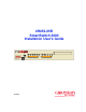
2H253-25R SmartSwitch 2200 Installation User’s Guide FAST ETHERNET WORKGROUP SWITCH LED MODE 2 1 RX-TX DPX-SPD 2H253-25R 9034006 PWR CPU RESET COM 4 3 6 5 8 7 10 9 12 11 14 13 16 15 18 17 20 19 22 21 24 23
Only qualified personnel should perform installation procedures. NOTICE Cabletron Systems reserves the right to make changes in specifications and other information contained in this document without prior notice. The reader should in all cases consult Cabletron Systems to determine whether any such changes have been made. The hardware, firmware, or software described in this manual is subject to change without notice.
FCC NOTICE This device complies with Part 15 of the FCC rules. Operation is subject to the following two conditions: (1) this device may not cause harmful interference, and (2) this device must accept any interference received, including interference that may cause undesired operation. NOTE: This equipment has been tested and found to comply with the limits for a Class A digital device, pursuant to Part 15 of the FCC rules.
CABLETRON SYSTEMS, INC. PROGRAM LICENSE AGREEMENT IMPORTANT: THIS LICENSE APPLIES FOR USE OF PRODUCT IN THE FOLLOWING GEOGRAPHICAL REGIONS: CANADA MEXICO CENTRAL AMERICA SOUTH AMERICA BEFORE OPENING OR UTILIZING THE ENCLOSED PRODUCT, CAREFULLY READ THIS LICENSE AGREEMENT. This document is an agreement (“Agreement”) between You, the end user, and Cabletron Systems, Inc. (“Cabletron”) that sets forth your rights and obligations with respect to the Cabletron software program (“Program”) in the package.
If the Program is exported from the United States pursuant to the License Exception TSR under the U.S.
CABLETRON SYSTEMS SALES AND SERVICE, INC. PROGRAM LICENSE AGREEMENT IMPORTANT: THIS LICENSE APPLIES FOR USE OF PRODUCT IN THE UNITED STATES OF AMERICA AND BY UNITED STATES OF AMERICA GOVERNMENT END USERS. BEFORE OPENING OR UTILIZING THE ENCLOSED PRODUCT, CAREFULLY READ THIS LICENSE AGREEMENT. This document is an agreement (“Agreement”) between You, the end user, and Cabletron Systems Sales and Service, Inc.
5. UNITED STATES GOVERNMENT RESTRICTED RIGHTS. The enclosed Product (i) was developed solely at private expense; (ii) contains “restricted computer software” submitted with restricted rights in accordance with section 52.227-19 (a) through (d) of the Commercial Computer Software-Restricted Rights Clause and its successors, and (iii) in all respects is proprietary data belonging to Cabletron and/or its suppliers.
CABLETRON SYSTEMS LIMITED PROGRAM LICENSE AGREEMENT IMPORTANT: THIS LICENSE APPLIES FOR THE USE OF THE PRODUCT IN THE FOLLOWING GEOGRAPHICAL REGIONS: EUROPE MIDDLE EAST AFRICA ASIA AUSTRALIA PACIFIC RIM BEFORE OPENING OR UTILIZING THE ENCLOSED PRODUCT, CAREFULLY READ THIS LICENSE AGREEMENT.
If the Program is exported from the United States pursuant to the License Exception TSR under the U.S.
DECLARATION OF CONFORMITY Application of Council Directive(s): Manufacturer’s Name: Manufacturer’s Address: European Representative Name: European Representative Address: Conformance to Directive(s)/Product Standards: Equipment Type/Environment: 89/336/EEC 73/23/EEC Cabletron Systems, Inc. 35 Industrial Way PO Box 5005 Rochester, NH 03867 Mr. J.
x
Contents Figures .......................................................................................................................................... xiii Tables............................................................................................................................................xiv ABOUT THIS GUIDE Using This Guide............................................................................................................xv Structure of This Guide ................................
3 INSTALLATION 3.1 3.2 3.3 3.4 3.5 4 TROUBLESHOOTING 4.1 4.2 4.3 A B.5 xii Device Specifications ......................................................................................A-1 Physical Properties .........................................................................................A-1 Electrical Specifications ..................................................................................A-2 Environmental Requirements..................................................................
Figures Figure 1-1 3-1 3-2 3-3 3-4 3-5 3-6 4-1 4-2 B-1 B-2 B-3 B-4 B-5 Page The 2H253-25R SmartSwitch 2200................................................................................. 1-1 Tabletop or Shelf Installation........................................................................................... 3-4 Attaching the Strain-Relief Bracket ................................................................................. 3-5 Attaching the Rackmount Brackets ......................................
Tables Table Page 3-1 Contents of 2H253-25R Carton........................................................................................ 3-2 4-1 LANVIEW LEDs .............................................................................................................. 4-2 4-2 Troubleshooting Checklist ............................................................................................... 4-5 A-1 COM Port Pin Assignments ..............................................................................
About This Guide Welcome to the 2H253-25R SmartSwitch 2200 Installation User’s Guide. This guide describes the 2H253-25R SmartSwitch 2200 device and provides information concerning network requirements, installation, and troubleshooting. For information about how to use Local Management to configure and manage the 2H253-25R, refer to the Cabletron Systems SmartSwitch Series 2E253, 2H252, 2H253 and 2H258 Local Management User’s Guide.
Related Documents Chapter 4, Troubleshooting, describes the function of the LANVIEW LEDs, which can help to quickly diagnose network/operational problems. Appendix A, Specifications, contains information on functionality and operating specifications, connector pinouts, environmental requirements, and physical properties.
Document Conventions The HSIM-W6 Installation Guide, the HSIM-W84 Installation Guide, and the WAN Series Local Management User’s Guide are included on the QuickSET CD-ROM and, along with the other manuals listed above, can be obtained from the World Wide Web in Adobe Acrobat Portable Document Format (PDF) at the following site: http://www.cabletron.com/ NOTE All documentation for the Cabletron Systems SecureFast VLAN Manager software is contained on the VLAN Manager CD-ROM.
1 Introduction This chapter introduces the 2H253-25R SmartSwitch 2200 device and provides information about how to obtain additional support from Cabletron Systems. Important Notice Depending on the firmware version used in the 2H253-25R, some features described in this document may not be supported. Refer to the Release Notes shipped with the 2H253-25R to determine which features are supported. 1.
Overview The 2H253-25R is used to connect individual high-bandwidth user devices, such as workstations, or to provide a central switching point for multiple 10/100 Mbps Fast Ethernet segments. The optional HSIMs provide high speed uplinks to networking technologies such as Fast Ethernet, Gigabit Ethernet, Fiber Distributed Data Interface (FDDI), Wide Area Network (WAN), and Asynchronous Transfer Mode (ATM). Some HSIMs can provide additional Fast Ethernet ports in varying media types.
Overview When Auto-Negotiation is supported at both ends of a link, the two devices dynamically adjust to full or half duplex operation based on the maximum capability that can be reached between the two devices. If the device connected to the 2H253-25R cannot auto-negotiate, the 2H253-25R operates according to the capabilities of the other device. 1.1.
Overview SmartTrunk, also referred to as SmartTrunking, is Cabletron Systems’ terminology for load balancing or load sharing. SmartTrunk provides the ability to take full advantage of the network’s redundant bandwidth. SmartTrunk divides network traffic across multiple ports in parallel to provide additional throughput. The SmartTrunk application can be used with any of Cabletron Systems’ switch modules (except ATM modules).
Overview 1.1.9 Rate Limiting The Rate Limiting feature enables the SmartSwitch device to control traffic rates on a per-port, per-priority basis. The network administrator can configure a rate limit (from 100 kbps to 1 Gbs) for a given port with an associated list of IEEE 802.1p priorities (which can include one, some, or all of the eight priority levels defined in 802.1p). Each rate limit is specified as an inbound or an outbound limit.
Overview 1.1.11 GARP Switch Operation Some or all ports on the switch may be activated to operate under the Generic Attribute Registration Protocol (GARP) applications, GARP VLAN Registration Protocol (GVRP) and/or GARP Multicast Registration Protocol (GMRP). GARP is a protocol, or set of rules, that outlines a mechanism for propagating the port state and/or user information throughout a bridged LAN to keep track of users and VLANs on the network fabric.
Overview 1.1.15 Optional HSIMs and VHSIMs Optional HSIMs and VHSIMs are available from Cabletron Systems for additional connectivity to various networking technologies. The HSIMs and VHSIMs available for the 2H253-25R are listed in the Release Notes shipped with the device. 1.1.16 Standards Compatibility The 2H253-25R is fully compliant with the IEEE 802.3, 802.3u, 802.3x, 802.1D, and 802.1Q standards. The 2H253-25R provides IEEE 802.
Getting Help 1.2 GETTING HELP For additional support related to this device or document, contact Cabletron Systems using one of the following methods: World Wide Web http://www.cabletron.com/ Phone (603) 332-9400 Internet mail support@cabletron.com FTP ftp://ftp.cabletron.com/ Login anonymous Password your email address To send comments or suggestions concerning this document, contact the Cabletron Systems Technical Writing Department via the following email address: TechWriting@cabletron.
2 Network Requirements Before installing the 2H253-25R, review the requirements and specifications referred to in this chapter concerning the following: • SmartTrunk (Section 2.1) • 10BASE-T Twisted Pair Network (Section 2.2) • 100BASE-TX Twisted Pair Network (Section 2.3) The network installation must meet the requirements to ensure satisfactory performance of this equipment. Failure to do so will produce poor network performance. NOTE 2.
100BASE-TX Network 2.3 100BASE-TX NETWORK The two RJ21 connectors on the front panel of the 2H253-25R each provide 12 fixed ports (ports 1 through 24) that support Category 5 UTP cabling. The device at the other end of the twisted pair segment must meet IEEE 802.3u 100BASE-TX Fast Ethernet network requirements for the devices to operate at 100 Mbps. Refer to the Cabletron Systems Cabling Guide for details.
3 Installation Only qualified personnel should install the 2H253-25R. NOTE Read the Release Notes shipped with the device to check for any exceptions to the supported features and operation documented in this guide. This chapter provides the instructions required to install the 2H253-25R. A Phillips screwdriver is required to install options into the device or install the device into a rack. Follow the order of the sections listed below to correctly install the device.
Installing Options Table 3-1 Contents of 2H253-25R Carton Item Quantity 2H253-25R 1 Antistatic Wrist Strap 1 Console Cable Kit 1 Rackmount Kit 1 Strain-Relief Bracket 1 Manual Accessory Kit 1 Power Cord 2 3. Remove the tape seal on the non-conductive bag to remove the 2H253-25R. 4. Perform a visual inspection of the device for any signs of physical damage. Contact Cabletron Systems if there are any signs of damage. Refer to Section 1.2 for details. 3.
Installing the Device 3.3.1 Tabletop or Shelf Installation The following two subsections provide guidelines for installation on a tabletop or shelf. Guidelines for Tabletop and Shelf Installations Tabletop and shelf installations must be within reach of the network cabling and meet the requirements listed below: • Locate the 2H253-25R within seven feet of an appropriately grounded power receptacle that meets the power supply requirements listed in Appendix A.
Installing the Device C B FAST ETHERNET WORKGROUP SWITCH LED MODE 2 1 RX-TX 4 3 6 5 8 7 10 9 12 11 14 13 16 15 18 17 20 19 22 21 24 23 DPX-SPD A 2H253-25R PWR CPU RESET COM D A = 15 cm (6 in) B = 57 cm (22.5 in) C = 53 cm (21 in) D = 213 cm (7 ft) 2762-02 Figure 3-1 3.3.
Installing the Device Installation Rack mounting the 2H253-25R involves the following: • Attaching the strain-relief bracket • Rack mounting the 2H253-25R (attaching the mounting brackets and fastening the device to the rack) Attaching the Strain-Relief Bracket Attach the strain-relief bracket to the 2H253-25R as follows: 1. Locate the strain-relief bracket and four 8-32 x 5/16-inch pan-head screws in the rackmount kit.
Installing the Device Rack Mounting the 2H253-25R Proceed as follows to install the 2H253-25R into a 19-inch rack: 1. There are several mounting holes in the rackmount brackets and the bottom of the chassis so that each mounting bracket may be adjusted forward or backward to mount the device further into, or out of the rack, depending on the installation requirements. Position the rackmount brackets over the appropriate holes. 2. Locate the four 6-32 x 1/4-inch flathead screws in the rackmount kit.
Installing the Device 3.3.3 NOTE Connecting Power The two power supplies in the 2H253-25R have automatic voltage sensing that allows connection to power sources ranging from 100–125 Vac, 2.5 A or 200–240 Vac, 1.25 A, 50/60 Hz. To connect the 2H253-25R to the power sources, proceed as follows: 1. Plug each power cord into a grounded wall outlet, see Figure 3-5. To take advantage of the load sharing and redundancy capabilities, each power cord must be plugged into a separate dedicated ac outlet.
Connecting to the Network 2. Observe the LANVIEW LEDs. After a successful boot, the PWR LED turns ON (green). If the PWR LED is amber, there is no power redundancy. Check the power cord connections and the power source. If there are no problems with the power cord connections or power source and the PWR LED is still amber, contact Cabletron Systems for support. Refer to Section 1.2 for details. 3.
Connecting to the Network Receive (RX) LED MODE LED MODE Switch in RX–TX position RX-TX Transmit (TX) DPX-SPD P SWITCH GROU RNET WORK FAST ETHE 2 1 LED MODE 4 3 6 5 8 7 10 9 12 11 14 13 16 15 18 17 20 19 22 21 24 23 RX-TX DPX-SPD PWR CPU RESET COM 2H253-25R Screw LED MODE Switch RJ21 Screw 2762-07 Figure 3-6 Straight Cable Connection 3. Tighten the two screws on the RJ21 straight cable connector to secure it to the device.
Completing the Installation c. Verify that the 100BASE-TX device at the other end of the twisted pair segment is powered up. d. Check the cable for continuity. e. If a link is not established, contact Cabletron Systems for technical support. Refer to Section 1.2 for details. 5. Repeat steps 1 through 4 above, until all connections have been made. 3.
4 Troubleshooting This chapter provides information concerning the following: • Using LANVIEW (Section 4.1) • Troubleshooting Checklist (Section 4.2) • Using the RESET Button (Section 4.3) 4.1 USING LANVIEW The 2H253-25R uses Cabletron Systems’ built-in visual diagnostic and status monitoring system called LANVIEW. The LANVIEW LEDs (Figure 4-1) allow quick observation of the network status to aid in diagnosing network problems.
Using LANVIEW The LED MODE switch is located on the front panel of the 2H253-25R as shown in Figure 4-1. This switch enables the user to change the function of the port LEDs. When the LED MODE switch is moved to the left, the LEDs indicate the receive (RX) and transmit (TX) status of the respective fixed ports (ports 1 through 24).
Using LANVIEW Table 4-1 LANVIEW LEDs (Cont’d) LED Color State Recommended Action CPU Off Power off. Power up device. Red Blinking. Hardware failure has occurred. Contact Cabletron Systems for assistance. Solid. Resetting, normal power up reset. If the LED remains Red for several minutes, contact Cabletron Systems for assistance. Blinking. Crippled. Contact Cabletron Systems for assistance. Solid. Testing.
Using LANVIEW Table 4-1 LANVIEW LEDs (Cont’d) LED Color State Recommended Action TX (Transmit) Off Port enabled, and no activity. 1. Ensure that the STA is enabled and that there is a valid link. 2. Contact Cabletron Systems for assistance. Should flash green every two seconds indicating BPDUs being sent if STA is enabled and there is a valid link. Green Flashing. Indicates activity. Rate indicates data rate. None. Amber Blinking. Port in standby. 1. Ensure that the port is not disabled. 2.
Troubleshooting Checklist 4.2 TROUBLESHOOTING CHECKLIST If the 2H253-25R is not working properly, refer to Table 4-2 for a checklist of possible problems, causes, and recommended actions to resolve the problem. Table 4-2 Troubleshooting Checklist Problem Possible Cause Recommended Action All LEDs are OFF. Loss of power. Check for proper connection of the power cable and its access to a live outlet. Installed improperly.
Troubleshooting Checklist Table 4-2 Troubleshooting Checklist (Cont’d) Problem Possible Cause Recommended Action Cannot contact the 2H253-25R through in-band management. IP address not assigned. Refer to the SmartSwitch Series 2E253, 2H252, 2H253, and 2H258 Local Management User’s Guide for IP address assignment procedure. Port is disabled. Enable port. Refer to the SmartSwitch Series 2E253, 2H252, 2H253, and 2H258 Local Management User’s Guide for instructions to enable/disable ports.
Troubleshooting Checklist Table 4-2 Troubleshooting Checklist (Cont’d) Problem Possible Cause Recommended Action User parameters (IP address, Device and Module name, etc.) were lost when the 2H253-25R power was cycled or the front panel RESET button was pressed. 1. Position of Mode switch (7), NVRAM Reset, was changed sometime before either cycling power or pressing the RESET button, causing the user-entered parameters to reset to factory default settings. 2.
Using the RESET Button 4.3 USING THE RESET BUTTON The RESET button shown in Figure 4-2 resets and re-initializes the 2H253-25R. ! CAUTION Pressing the RESET button resets the device, and all current switching being performed by the device is halted. A network downtime of up to two minutes will result from this action.
A Specifications This appendix provides operating specifications for the Cabletron Systems 2H253-25R. Cabletron Systems reserves the right to change these specifications at any time without notice. A.1 DEVICE SPECIFICATIONS Processors: Intel i960 RISC processor Power PC Dynamic Random Access Memory (DRAM): 20 MB expandable to 32 MB FLASH Memory: 8 MB Shared Memory: 4 MB A.2 PHYSICAL PROPERTIES Dimensions: 7.11H x 43.18W x 46.99D (cm) 2.8H x 17W x 18.5D (in) Approximate Weight (Unit): 8.
Electrical Specifications A.3 ELECTRICAL SPECIFICATIONS Line Input Range, Volts (V): 100–125 Vac 200–240 Vac Input Current, Amperes (A): 2.3 A 1.2 A Frequency, Hertz (Hz): 50/60 Hz 50/60 Hz Input Power, Volt Amperes (VA:) 250 VA 250 VA A.4 ENVIRONMENTAL REQUIREMENTS Operating Temperature: 5°C to 40°C (41°F to 104°F) Storage Temperature: -30°C to 73°C (-22°F to 164°F) Operating Relative Humidity: 5% to 90% (non-condensing) A.
COM Port Pinout Assignments A.6 COM PORT PINOUT ASSIGNMENTS The COM port is a serial communications port that supports Local Management or connection to a UPS. Table A-1 shows the COM port pin assignments. Table A-1 A.
B Optional Installations and Mode Switch Bank Settings ONLY QUALIFIED SERVICE PERSONNEL SHOULD ATTEMPT THE FOLLOWING PROCEDURES. NUR QUALIFIEZIERTE SERVICE PERSONNAL DIE FOLGENDE PROCEDURE FOLGEN SOLLTEN. SOLAMENTE PERSONAL CALIFICADO DEBE INTENTAR ESTE PROCEDIMIENTO.
Removing the Chassis Cover B.2 REMOVING THE CHASSIS COVER This section describes how to remove the 2H253-25R chassis cover. DO NOT REMOVE THE COVER FROM THE 2H253-25R WHILE POWER IS APPLIED TO THE UNIT. HAZARDOUS VOLTAGES ARE PRESENT AND COULD CAUSE PERSONAL INJURY AND/OR DAMAGE THE UNIT. DO NOT POWER UP THE 2H253-25R AGAIN UNTIL THE COVER AND SCREWS ARE IN PLACE. DECKEL VON DAS 2H253-25R NICHT ABZIEHEN UNTER SPANNUNG. GEFAHR FÜR DAS PERSONNAL UND/ODER DAS GERÄT WEGEN GEFÄHRLICHE SPANNUNGEN ENSTEHT.
Removing the Chassis Cover To remove the chassis cover, proceed as follows: 1. Disconnect the 2H253-25R from the network as follows: a. Unplug both power cords from the rear of the chassis. TURN OFF THE 2H253-25R BY UNPLUGGING THE POWER CORD FROM THE REAR OF THE CHASSIS. AM HINTEN DES 2H253-25R STECHEI ABZIEHEN UM AUS ZU SCHALTEN. APAGUE EL 2H253-25R DESENCHUFE EL CABLE DE LA UNIDAD. TIP Before performing step b, mark the cables connected to the 2H253-25R according to their associated port numbers.
Removing the Chassis Cover Screws (4) Chassis Cover Front Panel Chassis Note: If the device was rack mounted, the four screws fastening the cover to the front panel are removed and installed along with the rackmount brackets.
Setting the Mode Switches B.3 SETTING THE MODE SWITCHES Figure B-2 shows the location of the mode switches and the switch settings for normal operation. These switches are set at the factory and rarely need to be changed. Switch definitions and positions are as follows: • Switches 1 through 4 – For Cabletron Systems use only. • Switch 5 – COM Port Autobaud. The default (OFF) position enables Autobaud sensing on the COM port for Local Management sessions.
SIMM Upgrade DO NOT attempt a Forced BootP unless a BootP server has been configured for the 2H253-25R. The BootP server references the location of a station acting as a Trivial File Transfer Protocol (TFTP) server containing the 2H253-25R image file. When the position of Switch 6 is changed and the power is cycled to the 2H253-25R, the device requests the image file location from the BootP server and uses TFTP to download the image from the TFTP server.
SIMM Upgrade B.4.1 Locating SIMMs Figure B-3 shows the two locations of the DRAM SIMM connector. TOP VIEW WITHOUT COVER Redundant Power Supply Primary Power Supply DRAM FRONT PANEL 2504-84 Figure B-3 B.4.2 ! SIMM Slot Locations Installing the DRAM SIMM Observe all antistatic precautions when handling sensitive electronic equipment. CAUTION To install a DRAM SIMM, refer to Figure B-4 and proceed as follows: 1.
SIMM Upgrade 2. Pivot the SIMM downward so the connector clips align with the two side notches of the SIMM and the connector clips lock the SIMM into place.
Installing Optional HSIM or VHSIM Interface Modules B.5 INSTALLING OPTIONAL HSIM OR VHSIM INTERFACE MODULES Figure B-5 shows the location of the two connectors for an optional High HSIM or VHSIM. Depending on the HSIM or VHSIM installed, one or both connectors are used. NOTE The installation instructions for the optional HSIM or VHSIM are in the associated user’s guide.
Index Numerics D 100BASE-T requirements 2-2 10BASE-T requirements 2-1 2H253-25R description of 1-1 front panel 1-1 802.
Index L S LANVIEW LEDs 4-1 Local Management introduction to 1-6 SIMMs installing DRAM B-7 location B-7 SmartTrunk introduction to 1-3 Specifications A-1 Standards compatibility 1-7 Switching options introduction to 1-6 M Management use of 1-6 Memory upgrading B-6 Mode Switch setting B-5 T N Troubleshooting 4-1 checklist 4-5 Network connections 3-8 U P Unpacking 3-1 Physical properties A-1 Port Redirect Function, introduction to 1-4 Power connection 3-7 V R Redirect functions port and VLAN, in