
Owner manual


Appendix C: Optional Installations and Mode Switch Bank Settings
C-2 2M46-04R/2M46-04RDC User’s Guide
C.2 REMOVING THE CHASSIS COVER
This section describes how to remove the 2M46-04R chassis cover.
To remove the chassis cover, proceed as follows:
1. Disconnect the 2M46-04R from the network as follows:
a. For the 2M46-04RDC, flip the DC switches located on the back of
the chassis to the “OFF” position.
For the 2M46-04R, disconnect all power cords from the rear of the
chassis.
b. Disconnect all network cables attached to the 2M46-04R.
2. If the 2M46-04R is rack mounted, remove it from the rack and remove
the rackmount brackets (refer to Chapter 3, Installation).
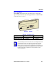
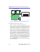
3. Use a Phillips screwdriver to remove the seven screws attaching the
cover to the chassis. (See Figure C-1.)
4. Remove the cover by sliding it back until it clears the front of the
chassis and then lifting it straight up and off of the chassis.
To reinstall the chassis cover, perform the removal procedures in reverse.
!
CAUTION
DO NOT REMOVE THE COVER FROM THE 2M46-04R
WHILE POWER IS APPLIED TO THE UNIT.
THIS UNIT MAY HAVE MORE THAN ONE POWER SUPPLY
CORD. DISCONNECT ALL POWER SUPPLY CORDS
BEFORE SERVICING.
DO NOT POWER UP THE 2M46-04R AGAIN UNTIL THE
COVER AND SCREWS ARE IN PLACE.
TIP
Before performing step b, mark the cables connected to the
2M46-04R according to their associated port numbers. This is
recommended for ease of reinstallation.