
User`s guide


5-24
Filters
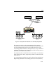
• Filter fields – destination address F-H (range, match) source
LAN = 1 (match).
Note that a Match flag is specified for both fields; this instructs the
ATX to filter any packets which match both fields (traffic from
LAN 1 and to addresses F-H on LAN 2).
Several methods are available to accomplish this. For example, the
combination filter could have been specified as follows:
• Filter identifier – port number of the port attached to LAN 1 as
a source
• Filter fields – destination address F-H (range, match).
If LAN 3 did not exist, then the recommended approach is to use
address table filters instead. Three filters (one for F, G, and H),
should be created which specify filter all destination and filter all
source.
This example is useful for illustrating three basic points concerning
ATX filters:
• The example illustrates a paradoxical concept: even though an
ATX is used to join network segments, it can also be used to
block selected traffic, or all traffic if desired, between joined
segments. The blocking mechanism is the filters you set up.
• Filters may be based upon various criteria: source address,
destination address, packet type, etc. In the example just
described, the filter criteria were source port and destination
address.
• A filter can only block (discard) packets which must cross the
ATX. The ATX in the example can only filter traffic that travels
from LAN 1 to LAN 2 (or from LAN 2 to LAN 1). An ATX filter
can prevent LAN 1 stations from accessing the sensitive-data
computers on LAN 2 but cannot prevent station E from
accessing these computers. The reason is that station E is on the
same LAN as the sensitive-data computers and therefore does
not need to use the ATX to access them.