
User`s guide


2-6
Installing and Connecting to the Network
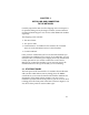
Figure 2-3. LED Activity During Normal Operation
Power-up Diagnostics Sequence
To observe the power-up sequence completely, you may want to
repeat it. To restart the power-up sequence, turn the power switch
off, then on again, or press the reset button above the power
Layer 1
Packet Processing Engine
POWER STATUS
ENGINE STATUS
TURBO STATUS
SUPPLY A
SUPPLY B
ON if
redundant
FDDI modules
(3F00-01 and 3F55-01)
WRAP
THRU
RX
Token Ring modules
(3T02-04 and 3T01-04)
RX
TX
ST
16 Power
Proc
(16 LED ON if set
for 16Mbps ring speed)
Ethernet modules
(3E02-04 and 3E08-04)
10BASE-T or 10BASE-FL
LINK
COL
RX
TX Power
Proc
LINK LED is
ON if module
is connected
Ethernet modules
(3E07-04 and 3E05-04)
10BASE2 or AUI
TX
RX Proc
Power
= OFF
= ON
= FLASHING
Fast Ethernet modules
(3H08-04, 3H02-04 and 3H01-04)
PROC
TX PWR
RING A
RING B