
User`s guide


FDDI Dual-Attached Intelligent Module User Guide Index-1
INDEX
Numerics
3F00-01
Front Panel 1-3
LEDs 1-4
3F55-01
Front Panel 1-3
LEDs 1-4
A
A and B keying 2-9
C
configuration options
dual-attached station 2-2
dual-homed single-attached
station 2-3
optical bypass switch 2-5
single-attached station 2-4
configuration tools 3-1
configuration variable
SMT 7.3 3-3
configuration variables
SMT version 6.2 3-2
connecting
dual attached station 2-11
dual-homed single-attached
station 2-12
optical bypass switch 2-13
single-attached station 2-12
D
diagnostic tests
power-up 5-1
diagnostics tests
operational 5-3
displaying
modual status 4-2
port statistics 4-2
port status 4-2
dual-attached station
about 2-2
dual-homed single-attached station
about 2-3
connecting 2-12
K
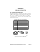
keying, media interface
connectors 2-8
L
LEDs
meaning
3F00-01 5-2
3F55-01 5-2
power-up sequence
3F00-01 2-6
3F55-01 2-7
types
3F00-01 1-4
3F55-01 1-4
M
M and S keying 2-10
media interface connectors,
keying 2-8
module status 4-5
modules
adding 6-1
swapping 6-2
O
operational diagnostics 5-3
optical bybass switch
cable pinouts B-1
optical bypass switch
about 2-5
connecting 2-13