
- Cabletron User's Guide SmartSwitch Interface Modules 6H258-17, 6H259-17


Setting the Mode Switches
B-2 Switch Settings, Upgrades, and Installations
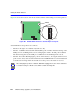
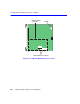
Figure B-1 shows the location of the mode switches and the switch settings for normal operation.
Figure B-1 Module Mode Switch Location/Component Layout
Switch definitions and positions are as follows:
• Switches 1 through 4 – For Cabletron Systems use only.
• Switch 5 – COM Port Autobaud. The default (OFF) position enables Autobaud sensing on the
COM port for Local Management sessions. Changing the switch to the ON position disables
Autobaud sensing and sets the COM port to 9600 baud for Local Management sessions.
• Switch 6 – Forced BootP. Changing the position of this switch (i.e., moving the switch from one
position to the other) clears download information from NVRAM and forces the SmartSwitch
to download a new image file from a BootP server after power to the chassis is restored.
NOTE
After changing the position of switch 6, DO NOT reapply power to the chassis until there
is a station acting as a BootP server, which contains the image file.
DRAM
MODE SWITCH
1
2
3
4
5
6
7
8
OFF ON
2159_34