
Specifications


Ethernet Data Frames 4-3
Ethernet Data Frames
Ethernet Data Frames
Previously it was shown how Ethernet data signals are transformed into
bits. Before these bits are sent onto an Ethernet network, they must be
formatted into specific groups called data frames. Data frames are strings
of bytes (eight bits equal one byte) which contain addressing, timing,
protocol, and error correction information as well as the data being sent.
The packet structure used in IEEE 802.3 and Ethernet is shown in
Figure 4-2.
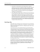
Figure 4-2. Ethernet Data Frames
Each section of the frame is described as follows:
• Preamble: The preamble indicates the beginning of frame transmission.
The preamble allows for frame timing at the receiving station. The
signal pattern is a repeating pattern of alternating ones and zeroes for
a total of 56 bits (7 bytes).
• Start Frame Delimiter (SFD): The SFD signal pattern is 10101011 for a
total of 8 bits (1 byte). It follows the preamble and indicates the start of
information by the last two bits, 11.
• Destination Address: The address of the station, or stations, that the
data frame is intended for. It follows the SFD and is 48 bits (6 bytes) in
length.
• Source Address: Follows the destination address and indicates the
address of the station initiating the transmission. The source address is
48 bits (6 bytes) in length.
• Length Field: The length field follows the source address and indicates
the length of the data field. The length field is 16 bits (2 bytes) long. In
Ethernet version 1.0 or version 2.0, this field is called a type field. The
type field will usually indicate the packet protocol (e.g., TCP/IP, XNS,
DECNet, Novell IPX, etc.).
Preamble SFD
Dest.
Address
Source
Address
Length Data
CRC
Data Frame
7 Bytes 1 Byte 6 Bytes 6 Bytes 2 Bytes 46-1500 Bytes 4 Bytes
1913-06