
Specifications


Spanning Tree Operation
9-14 Ethernet Bridge Operation
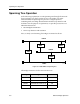
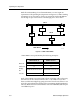
There is one final data loop present. JANET is bridging from LAN A to
LAN B. The bridge entities recognize the data loop condition by
monitoring the incoming BPDUs. Upon seeing BPDUs coming in through
both of its ports, all originating from the root, it realizes that there is more
than one path to the root bridge. By using the order of comparisons shown
above, the bridge entity can make an intelligent decision as to whether the
port in question should be made part of the active topology or should be
sent to the BLOCKING state.
Figure 9-6 shows the resulting topology. There is only one data path
between any two end stations within this bridged LAN. All data loops
have been identified and resolved. We now have built-in redundancy that
can be used if one or more of the active bridge components fail.
Figure 9-6. Resulting Topology after Spanning Tree
LAN A
LAN B
LAN C
ANN JANET
SAM
EVENIN
Port 2 Blocking Port 2 Blocking
Port 1
Port 2
Port 1Port 1
Port 1
Port 2
1913-36