SmartSwitch 9000 9F426-03 User’s Guide 903number
Notice Notice Cabletron Systems reserves the right to make changes in specifications and other information contained in this document without prior notice. The reader should in all cases consult Cabletron Systems to determine whether any such changes have been made. The hardware, firmware, or software described in this manual is subject to change without notice.
Notice FCC Notice This device complies with Part 15 of the FCC rules. Operation is subject to the following two conditions: (1) this device may not cause harmful interference, and (2) this device must accept any interference received, including interference that may cause undesired operation. NOTE: This equipment has been tested and found to comply with the limits for a Class A digital device, pursuant to Part 15 of the FCC rules.
Notice DOC Notice This digital apparatus does not exceed the Class A limits for radio noise emissions from digital apparatus set out in the Radio Interference Regulations of the Canadian Department of Communications. Le présent appareil numérique n’émet pas de bruits radioélectriques dépassant les limites applicables aux appareils numériques de la class A prescrites dans le Règlement sur le brouillage radioélectrique édicté par le ministère des Communications du Canada.
Notice Safety Information CLASS 1 LASER TRANSCEIVERS The FPIM-05 and FPIM-07 are Class 1 Laser Products CLASS 1 LASER PRODUCT The FPIM-05 and FPIM-07 use Class 1 Laser transceivers. Read the following safety information before installing or operating these adapters. The Class 1 laser transceivers use an optical feedback loop to maintain Class 1 operation limits. This control loop eliminates the need for maintenance checks or adjustments. The output is factory set, and does not allow any user adjustment.
Notice Safety Information CLASS 1 LASER TRANSCEIVERS Laser Radiation and Connectors When the connector is in place, all laser radiation remains within the fiber. The maximum amount of radiant power exiting the fiber (under normal conditions) is -12.6 dBm or 55 x 10-6 watts. Removing the optical connector from the transceiver allows laser radiation to emit directly from the optical port. The maximum radiance from the optical port (under worst case conditions) is 0.8 W cm-2 or 8 x 10³ W m2 sr-1.
Notice DECLARATION OF CONFORMITY Application of Council Directive(s): Manufacturer’s Name: Manufacturer’s Address: European Representative Name: European Representative Address: Conformance to Directive(s)/Product Standards: Equipment Type/Environment: 89/336/EEC 73/23/EEC Cabletron Systems, Inc. 35 Industrial Way PO Box 5005 Rochester, NH 03867 Mr. J.
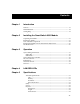
Contents Chapter 1 Introduction Features........................................................................................................................... 1-1 Related Manuals............................................................................................................ 1-4 Getting Help .................................................................................................................. 1-4 Chapter 2 Installing the SmartSwitch 9000 Module Unpacking the Module...........
Contents Appendix A FPIM Specifications FPIM-00 and FPIM-01..................................................................................................A-1 FPIM-02 and FPIM-04..................................................................................................A-2 FPIM-05 and FPIM-07..................................................................................................
Chapter 1 Introduction The 9F426-03 FDDI SmartSwitch® Module, shown in Figure 1-1, is a four port switch module with three front panel FDDI interfaces and one INB-2 backplane interface. The external FDDI networks are connected to the module using standard Cabletron FPIMs on the front panel. The 9F426-03 module employs SmartSwitch ASIC, a high performance switch design, and an Intel i960 microprocessor. Features Processor The 9F426-03 is equipped with an advanced Intel i960 microprocessor.
Introduction Cabletron enterprise MIBs. In addition, the front panel provides LEDs for FDDI link status per port, as well as transmit and receive activity. Full Duplex The 9F426-03 may be configured to operate in either Simplex or Full Duplex mode. This is selected though local management or via SNMP. Connectivity The 9F426-03 module has one interface to the INB-2 and three front panel FDDI interfaces. The front panel connections are via standard Cabletron FPIMs.
Introduction FDDI 9F426-03 SMB CPU INB Figure 1-1.
Introduction Related Manuals The manuals listed below should be used to supplement the procedures and technical data contained in this manual.
Chapter 2 Installing the SmartSwitch 9000 Module This module uses FPIMs for the front panel connections. They are not shipped with the module and must be purchased separately. For more information on FPIMs, see Appendix A. Unpacking the Module 1. Carefully remove the module from the shipping box. (Save the box and packing materials in the event the module must be reshipped.) 2. Remove the module from the plastic bag. Observe all precautions to prevent damage from Electrostatic Discharge (ESD). 3.
Installing the SmartSwitch 9000 Module Figure 2-1. Installing an FPIM User Accessible Components Figure 2-2 shows the various components that are accessible to the user. These consist of an eight-position DIP switch (explained below), replaceable PROMs and sockets for RAM. These will be used for future upgrades. Instructions for installing the components will be supplied with the upgrade kit.
Installing the SmartSwitch 9000 Module SMB-1 PROM Flash SIMM Socket Boot PROM i960 Processor DIP Switch 1 2 3 4 5 6 7 8 Local DRAM Socket Figure 2-2. User Accessible Components An eight-position DIP switch is located on the module card as shown in Figure 2-2. The function of the switches are listed in Table 2-1.
Installing the SmartSwitch 9000 Module See the Cautions at the end of this table. Table 2-1. Function of DIP Switch Switch Function Description 8 Clear Password 1 When toggled, this switch clears user-entered passwords stored in NVRAM, and restores the default passwords. Once reset you can use the defaults or enter new passwords. Clear NVRAM 2 The module uses NVRAM to store user entered parameters such as IP addresses, device name, etc.
Installing the SmartSwitch 9000 Module Installing the Module into the SmartSwitch 9000 Chassis To install the SmartSwitch 9000 module, follow the steps below: NOTE The INB Terminator Modules must be installed on the rear of the chassis before powering up this module. Refer to the INB Terminator Modules Installation Guide for information and installation procedure. 1. Remove the blank panel covering the slot in which the module is being installed.
Installing the SmartSwitch 9000 Module Plastic Tab Jack for ESD Wrist Strap Metal Back-Panel Module Module Guides Warning: Ensure that the circuit card is between the card guides. Lock down the top and bottom plastic tabs at the same time, applying even pressure. Figure 2-3.
Installing the SmartSwitch 9000 Module The Reset Switch The Reset switch is located under the top plastic tab as shown in Figure 2-4. Use the reset switch to reset the module’s processor, shutdown (power down) the module, and/or restart the module. • • • To reset the module’s i960 processor, press the reset switch twice within three seconds. To shutdown the module, press and hold the reset switch for three or more seconds. To restart the module, press the reset switch momentarily.
Installing the SmartSwitch 9000 Module 2-8
Chapter 3 Operation The 9F426-03 FDDI SmartSwitch Module is a four port switch module with three front panel FDDI interfaces and one INB-2 backplane interface. As shown in Figure 3-1, packets are received at the front panel FDDI ports and the INB-2 bus. These packets are converted into canonical format. The SmartSwitch ASIC circuitry decides from header information where the packets should be sent. They are then converted from canonical format to the proper format for that interface.
Operation SMB-1 Bus The SMB-1 is a 1Mbs management bus located within the SmartSwitch 9000. This bus is utilized by all diagnostic controllers in the system including connectivity modules, power supply modules and the environmental module. The SMB-1 transports inter-chassis information between system components, such as power and environmental information, as well as diagnostic messages. Periodic loop-back tests are performed by all modules that share this bus to ensure the validity of SMB-1.
Operation INB Interface Each module that attaches to the INB has an INB Network Interface Block (NIB). The INB NIB converts canonical frames to fixed length data blocks for transmission onto the INB. For data blocks received from the INB, the INB NIB reassembles the data blocks received from the INB back into canonical frames for transmission to the SmartSwitch ASIC then from the SmartSwitch ASIC to the front panel ports.
Operation i960 Core The i960 core provides the SNMP protocol stacks to support industry standard MIBs. Additionally, Cabletron enterprise extension MIBs are supported for each media type. Advanced management services, such as the Distributed LAN Monitor, telnet and network address to MAC address mapping, are also provided by the i960 core. The Host engine sends and receives packets via the CPU SmartSwitch ASIC Interface.
Chapter 4 LANVIEW LEDs The front panel LANVIEW LEDs indicate the status of the module and may be used as an aid in troubleshooting. Shown in Figure 4-1 is the LANVIEW LEDs of the 9F426-03 module. FDDI 9F426-03 System Status INB Receive INB Transmit SMB FDDI Receive CPU INB FDDI Transmit FDDI Status Figure 4-1.
LANVIEW LEDs The functions of the two System Status LEDs, System Management Bus (SMB) and the CPU, are listed in Table 4-1. Table 4-1. System Status (SMB and CPU) LEDs LED Color State Description Green Functional Fully operational. Yellow Testing Power-up Testing Yellow (Flashing) Crippled Not fully operational (i.e., one bad port). Yellow/Green Booting Blinks yellow and green while booting. Red Reset Normal power-up reset. Red (Flashing) Failed Fatal error has occurred.
LANVIEW LEDs The functions of the FDDI receive LEDs are listed in Table 4-4. Table 4-4. FDDI Receive LEDs LED Color State Yellow (Flashing) Activity Off No Activity The functions of the FDDI Transmit LEDs are listed in Table 4-5. Table 4-5. FDDI Transmit LEDs LED Color State Green (Flashing) Activity Off No Activity The FDDI status LEDs display the status when bridging to the front panel port. The “A” and “B” LEDs indicate the status of the A and B ports.
LANVIEW LEDs The functions of the FDDI Status LEDs are listed in Table 4-6. Table 4-6.
Chapter 5 Specifications Technical Specifications CPU Intel i960 RISC based microprocessor Memory 4 Meg. Flash Memory (expandable to 32 Meg.) 16 Meg. DRAM Standards ANSI FDDI X3T9.
Specifications Safety It is the responsibility of the person who sells the system to which the module will be a part to ensure that the total system meets allowed limits of conducted and radiated emissions. ! CAUTION This equipment meets the safety requirements of: • • • • • • • • UL 1950 CSA C22.2 No.
A FPIM Specifications This SmartSwitch 9000 module uses Fiber Port Interface Modules (FPIM) to provide front panel cable connections. The FPIMs are user-installable. See section titled Installing an FPIM on page 2-1. FPIM-00 and FPIM-01 The FPIM-00 and FPIM-01 provide a multimode fiber connection. The FPIM-00 uses a MIC-style connector and the FPIM-01 uses an SC-type connector. The specifications for both devices are listed in Table A-1. Table A-1.
FPIM Specifications Transmitter power parameters are listed in Table A-2. Table A-2. Transmitter Power Parameters Parameter Typical Value Worst Case Worst Case Budget Typical Budget 50/125 µm fiber -13.0 dBm -15.0 dBm 13.0 dB 17.5 dB 62.5/125 µm fiber -10.0 dBm -12.0 dBm 16.0 dB 20.5 dB 100/140 µm fiber -7.0 dBm -9.0 dBm 19.0 dB 23.5 dB Error Rate Better than 10-10 The link distance is up to 2 kilometers on the multimode fiber-optic cable as specified by ANSI MMF-PMD.
FPIM-05 and FPIM-07 FPIM-05 and FPIM-07 The FPIM-05 and FPIM-07 provide a Single-mode fiber connection. The FPIM-05 uses a MIC-style connector and the FPIM-07 uses an SC-type connector. The specifications for both devices are listed in Table A-4. Table A-4. FPIM-05 and FPIM-07 Specifications Parameter Typical Minimum Maximum Transmitter Peak Wave Length 1300 nm 1270 nm 1330 nm Spectral Width 60 nm - 100 nm Rise Time 3.0 nsec 2.7 nsec 5.0 nsec Fall Time 2.5 nsec 2.2 nsec 5.
FPIM Specifications A-4