
Installation guide


2-1
Chapter 2
SmartSwitch 9000-6 Slot Chassis
Installation
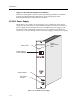
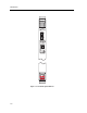
This chapter provides guidelines for choosing a site to install the SmartSwitch
9000-6 Slot Chassis. It also provides instructions on unpacking and rack mounting
the chassis. Installation instructions for the power supplies, fan tray, System
Monitor Module, and media interface modules are also provided.
Installation Requirements
The following guidelines must be followed to select a site for the SmartSwitch
9000-6 Slot Chassis. Failure to ensure that these guidelines are met may result in
installation difÞculties and/or unsatisfactory operation. Prior to beginning any
installation, ensure that the proposed location meets the following requirements:
¥ The site must have an unrestricted free surface area around the SmartSwitch
9000-6 Slot chassis, allowing for free movement of air. An open space of at least
84 high by 63.5 wide by 81.24 centimeters deep (29.5 high by 25 wide by 24
inches deep) is the minimum recommended.
¥ If the unit is installed in an enclosed equipment cabinet, the cabinet must have
a built-in cooling fan.
¥ The maximum theoretical heat dissipation of the SmartSwitch 9000-6 Slot
chassis is 8700 BTUs per hour. Actual heat dissipation varies depending on the
modules installed in the SmartSwitch 9000-6 Slot chassis. The temperature of
the location must be maintained between 5¡ and 40¡C (41¡ and 104¡F) with
changes in temperature no greater than 10¡C (18¡F) per hour.
Only qualiÞed personnel should perform installation procedures.