
Switch User's Guide

CSX400 and CSX400-DC User’s Guide 205
10
Troubleshooting
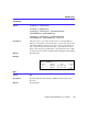
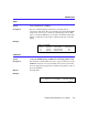
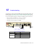
Use this chapter in conjunction with the LANVIEW status monitoring and diagnostic LEDs on the
CSX400 to diagnose power failures, collisions, cable faults and link problems. Figure 77 shows
the front panel LEDs. Table 24, Table 25, Table 26, Table 27, and Table 28 describe LED states.
If you are having difficulty installing and configuring the CSX400, perform the following steps:
• Review the CSX400 QuickSTART Guide to insure proper installation.
• Check that all cables and connectors have been attached properly.
• Verify that power has been applied to the CSX400.
Figure 77 CSX400 Front Panel LED
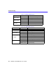
Table 24 CSX400 Hardware LED States
LED Color State
Power (PWR)
OFF Power off
GREEN Power on
Processor (CPU)
OFF Power off
RED Fault condition detected
GREEN (blinking) NORMAL
Power
CPU
Receive
Transmit
Collision
Transmit
Receive
Link
Status 1
Status 2
Test