E1100, E2100, AND E3100 SERIES ETHERNET NETWORK ADAPTERS INSTALLATION GUIDE Desktop Network Interface Products C A B L E T R O N S Y S T E M S, I N C.
NOTICE NOTICE Cabletron Systems reserves the right to make changes in specifications and other information contained in this document without prior notice. The reader should in all cases consult Cabletron Systems to determine whether any such changes have been made. The hardware, firmware, or software described in this manual is subject to change without notice.
FCC NOTICE FCC NOTICE This device complies with Part 15 of FCC rules. Operation is subject to the following two conditions: (1) this device may not cause harmful interference, and (2) this device must accept any interference received, including interference that may cause undesired operation. WARNING: This equipment has been tested and found to comply with the limits for a Class A digital device, pursuant to Part 15 of FCC Rules.
CONTENTS CONTENTS CHAPTER 1 1.1 1.2 1.3 INTRODUCTION Using This Manual ....................................................................1-1 The Adapter Features ...............................................................1-2 1.2.1 Connectivity ...................................................................1-2 1.2.2 Thin Ethernet Port .........................................................1-2 1.2.3 10BASE-T Twisted Pair Port ........................................1-2 1.2.
CONTENTS 2.11 Software Check List ................................................................2-15 2.12 Getting Help ............................................................................2-16 2.13 Specifications ...........................................................................2-18 2.13.1 Power Requirements ...................................................2-18 2.13.2 Environmental Requirements ....................................2-18 2.13.3 Safety ......................................
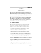
INTRODUCTION CHAPTER 1 INTRODUCTION This manual provides installation and reference information for the network adapters. The network adapters connect your PC to: a 10BASE-T twisted pair Ethernet network segment, a thin Ethernet 10BASE-2 coaxial network, a fiber optic network segment, or a transceiver via an AUI cable. The adapters incorporate Cabletron Systems’ LANVIEW LEDs.
INTRODUCTION 1.2 THE ADAPTER FEATURES The following sections outline the features of the adapters. 1.2.1 Connectivity The Cabletron Systems adapters connect your computer to an IEEE 802.3 Ethernet network. The various adapter models incorporate either an Ethernet 10BASE-T twisted pair port, a thin Ethernet coaxial BNC port, an SMT type fiber optic port, or an external transceiver via an AUI cable.
INTRODUCTION 1.2.4 Fiber Optic Ports The fiber optic ports on the adapter employs two ST type fiber optic connectors. The dark gray ST connector is the fiber optic receive port and light gray ST connector is the fiber optic transmit port. The ST connector fiber optic ports can utilize 50/125 µm, 62.5/125 µm, and 100/140 µm fiber optic cables. 1.2.5 Jabber Protection A built-in jabber protection scheme ensures that the network is not disabled due to the transmission of excessively long packets (jabber).
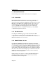
INTRODUCTION XMT CP RCV LNK or PWR CP XMT LNK Upper Port RCV RJ-45 Port RJ-45 Port LNK Lower Port RJ-45 Port BNC Port Dual Media Adapter Dual Port Adapter Figure 1-1. LANVIEW LEDs • Collision Present (CLN) This LED flashes when the adapter is transmitting to indicate that the adapter is detecting a collision condition on the network (red indicator). • Receive (RCV) network traffic This LED flashes to indicate that the adapter is receiving data packets from the network (yellow indicator).
INTRODUCTION 1.2.7 Software Software drivers, related software, and diagnostics are supplied by Cabletron Systems on floppy diskettes shipped with the adapter. The drivers support a variety of network platforms. Refer to the Network Software Installation Guide. The diagnostic program provided with the adapter allows you to check the adapter’s operation at various levels, through a series of tests.
INSTALLATION CHAPTER 2 INSTALLATION 2.1 ADAPTER MODELS The E1100, E2100, and E3100 Series network adapters are used for the specific computer bus architectures listed below: • E1100 Series - IBM Personal Computer XT, IBM Personal Computer AT, IBM Personal System/2 Models 25 or 30, or a compatible with an XT or an AT style bus. • E2100 Series - IBM Personal Computer AT, IBM Personal System/2 Model 30, or a compatible with an AT style bus.
INSTALLATION 2.1.1 Model Number References The descriptions of Ethernet adapter features use model numbers with a lower case x in them. The x indicates that any number from the model number reference chart applies to that feature. The model number E11xx indicates an E1100 series adapter with any media combination has the described feature. For example, an E1112 is an E1100 Series adapter with UTP and coax ports. A model with the suffix -X indicates a large memory option.
INSTALLATION 2.2.1 Unpacking the Adapter The network adapter and its software are shipped separately. The complete installation package should contain one conductive pouch with the adapter and this manual. The software is shipped in a shrink-wrapped package containing the software, a license agreement, and a Network Software Installation Guide. Carefully remove the conductive pouch from the box. Leave the adapter in the conductive pouch until you are ready to install it.
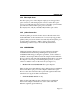
INSTALLATION Boot PROM Socket JP1 I/O Base Address JP2 ROM Enable Figure 2-1. The E1112 Adapter 2.2.4 Preparing the E2100 for Installation The E21xx Series employs a socket for an optional Boot PROM. All parameters except the I/O base address and PROM base address are set through software. Instructions are included for setting the I/O base address, and installing the Boot PROM. Figure 2-2, an E2112 adapter, shows the locations of the jumpers and Boot PROM socket.
INSTALLATION 2.3 SETTING THE I/O BASE ADDRESS JUMPER The I/O base address Jumper, JP1, must be set to one of four possible addresses before the adapter is installed. The I/O base address jumper sets the I/O (input/output) base address that identifies the adapter to the PC. The I/O base address is a hexadecimal field that distinguishes the adapter from other adapters that may be in the PC. Two shunts are supplied with the jumper in the event you want to use the 220 address setting.
INSTALLATION 2.4 I/O ADDRESS SPACE REQUIREMENTS The I/O address space for the E1100 and E2100 Series adapters occupies 20 Hex of the selected I/O base address. For example, if you select 220 Hex, the adapter I/O address range will extend through 23F Hex. Note that 23F lies within the address space (230 to 240) allotted to the bus mouse. If your system uses a bus mouse, address 220 cannot be used for the adapter because of the address conflict with the bus mouse.
INSTALLATION To install a Boot PROM, remove the Boot PROM from its packaging. Ensure that the legs of the Boot PROM are aligned in a 90° angle with the PROM body so the legs of the Boot PROM are perpendicular to the Boot PROM pin sockets. Insert the Boot PROM into the PROM socket so that the notch in the PROM is aligned with the notch in the socket as shown in Figure 2-5. Refer to the Boot PROM installation instructions included with the PROM for setting Boot PROM parameters.
INSTALLATION • Carefully remove the adapter from its protective pouch, and visually inspect it. • Remove the backplate (2, Fig. 2-6) from the selected slot (3) by removing the screw (1) holding the backplate in place, and sliding the backplate out of the slot as shown in Figure 2-6. Carefully insert the adapter into the expansion slot as shown in Figures 2-7 and 2-8. Orient the adapter (1) so the PC edge bus connector (2) is pointed down and the ports face out the back of the PC.
INSTALLATION 1 1. Adapter 2. PC Board Connector 3. Expansion Slot 2 3 Figure 2-7. Installing the E1100 Series Adapter 1 1. Adapter 2. PC Board Connector 3. Expansion Slot 2 3 Figure 2-8.
INSTALLATION Reinsert the screw removed in disassembly and replace the PC cover. Reattach the power and peripheral cables and turn on the power for the PC and the peripherals. 2.7 INSTALLING THE E3100 SERIES ADAPTERS This section contains instructions for preparing and installing your Cabletron Systems E3100 Series network adapter into your computer. The only hardware preparation for installing the E3100 Series adapter is the installation of an optional Boot PROM. 2.7.
INSTALLATION Boot PROM Socket Figure 2-9. The E3112 Adapter 2.7.3 Installing the E3100 Adapter To install the adapter in your computer, follow these instructions: • Turn off the power to the PC and peripherals and disconnect all power cords and cables. • Following the instructions in your computer user manual, using static discharge precautions, remove the cover from the computer. • Select the slot in which the adapter will be installed.
INSTALLATION 1 2 1. Backplate 2. Thumbscrew Figure 2-10. Micro Channel Backplate Detail CAUTION: The adapter is sensitive to static discharges. Hold it by the corners. Avoid contact with the PC bus edge connector or any of the components. Failure to observe all static precautions may result in damage to the adapter. • If you have not already done so, carefully remove the adapter from its protective pouch, and visually inspect it. • Remove the protective backplate (1, Fig.
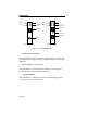
INSTALLATION • Align the adapter so the PC bus edge connector is lined up with the expansion slot (4) as shown in Figure 2-11. 1 5 2 3 4 1. 2. 3. 4. 5. Clip Adapter Edge Connector Expansion Slot Clip Figure 2-11. Installing the E3100 Series Adapter • Slide the adapter into the guide slots and firmly press, but do not force, the adapter into the expansion slot. The plastic clips on the adapter (1, 5, Figure 2-11) will snap into place as the adapter is inserted into the expansion slot.
INSTALLATION 2.8 COPYING THE ADF FILE After an E3100 Series adapter is installed in your computer and before using it, you must copy the Cabletron Adapter Description File (ADF) onto a backup copy of your system’s Reference Diskette. The ADF is supplied with your Cabletron software. The ADF provides Programmable Option Select Parameters for the System Configuration Utility. If necessary, you can change the parameters during this procedure.
INSTALLATION 2.10 TROUBLESHOOTING CHECK LIST FOR ADAPTERS • Make sure the adapter is installed and properly seated in the PC chassis connector. • On the adapter, if the coax port is used it is necessary to have a T and terminator attached to it. • If the adapter does not initialize, verify that the bus slot is operational by swapping the adapter with an adapter that you know is functioning. • Try swapping the adapter with a known working adapter.
INSTALLATION • The adapters use shared memory. VGA adapters will use the A block through C7FFF. Memory adapters will use the entire D block. If you don’t have a memory adapter installed, the D block is your best selection - otherwise the C8000 starting address can be used on the standard memory adapters. • If Windows is installed on an Ethernet client, then it is necessary to modify the SYSTEM.INI File. See the Network Software Installation Guide. • When using the packet driver version 4.
INSTALLATION • The contents of the AUTOEXEC.BAT, CONFIG.SYS, PROTOCOL.INI, and NET.CFG files (if applicable). You can contact Cabletron Systems Technical Support by: Phone: (603) 332-9400 FAX: (603) 335-4743 BBS: (603) 335-3358 (4 lines available) Cabletron Technical Support can also be reached over the Internet by sending email to: support@ctron.com Drivers are available for anonymous FTP download from: ctron.com (IP Address 134.141.197.
INSTALLATION 2.13 SPECIFICATIONS 2.13.1 Power Requirements E1100 Series +5 V @ ≤ 2.0 amps maximum +12 V @ ≤ 500 mA maximum with transceiver attached. E2100 Series +5 V @ ≤ 2.0 amps maximum +12 V @ ≤ 175 mA maximum with transceiver attached. E3100 Series +5 V @ ≤ 1.2 amps maximum +12 V @ ≤ 175 mA maximum with transceiver attached. 2.13.2 Environmental Requirements Operating Temperature: 0° to + 60°C (32° to 140°F) Operating Humidity: 10% to 90% (non-condensing) 2.13.
MAKING NETWORK CONNECTIONS CHAPTER 3 MAKING NETWORK CONNECTIONS This section contains instructions for connecting your adapter to an Ethernet network. An adapter can be connected to the network through either a media interface port or an AUI port on the adapter. You should have selected the port during the configuration procedures. If you did not, refer to the appropriate section for your adapter. We recommend that you run the diagnostic program before connecting your PC to a network segment.
MAKING NETWORK CONNECTIONS 12 3 4 5 6 7 8 RJ-45 Port RJ-45 Connector Figure 3-2. RJ-45 Connector RJ-45 Connections Type: Pin 1 2 3 4 TX+ TXRX+ No Connection RJ-45 connector Pin 5 6 7 8 No Connection RXNo Connection No Connection • Connect the twisted pair segment (4, Fig. 3-1) by inserting the RJ-45 connector (3) into the adapter’s RJ-45 port (2). • Check that the Link LED on the adapter is lit. The Link LED may not light until data has been transmitted out the 10BASE-T port.
MAKING NETWORK CONNECTIONS • Check the cable for continuity, and ensure that the cable is actually a twisted pair cable. • Check that the adapter is properly seated in the expansion slot. • Check that the twisted pair connection meets dB loss and cable specifications outlined in Section 3.1.2, below. If a link still has not been established, contact Cabletron Systems Technical Support (see Section 2.12, Getting Help). 3.1.
MAKING NETWORK CONNECTIONS • Delay - Must not exceed 1000 nsec for a 10BASE-T link. This delay limits maximum link segments to 200 meters. • Crosstalk - Crosstalk is caused by signal coupling between cable pairs within a multi-pair cable bundle. Crosstalk should not be a problem if the cable meets all other requirements. • Noise - Noise can be caused by either crosstalk or externally induced impulses.
MAKING NETWORK CONNECTIONS 1 3 2 1 3 2 5 View A 4 View B Figure 3-3. Attaching a Thin-Net Segment 3.2.2 Thin-Net Requirements • Cable - Must be 50 ohm RG-58A type coaxial cable. • Length - Must be no longer than 185 meters (607 ft.). • Termination - A 50 ohm terminator at the far ends of each thin-net segment. • Connections - A maximum of 30 connections may be used throughout a thin coaxial segment for host connections.
MAKING NETWORK CONNECTIONS 3.3 CONNECTING TO A FIBER OPTIC LINK SEGMENT The physical communication link consists of two fiber optic strands between the adapter and the other Ethernet fiber optic device on the link: Transmit (TX) and Receive (RX). The adapter Tx connects to Rx of the Ethernet device. The adapter Rx connects to Tx of the Ethernet concentrator. We recommend that you label the fiber optic cable to indicate which fiber is Receive and which is Transmit.
MAKING NETWORK CONNECTIONS Verify that the fiber strands are “crossed over” at the far end device, transmit to receive, by checking the labeling on each strand. Verify that the fiber connection meets the dB loss specifications outlined in Section 3.3.1, below. If a link still has not been established, contact Cabletron Systems Technical Support (see Section 2.12, Getting Help). 1 2 1. ST Port 2. ST Connector Figure 3-4. ST Fiber Optic Connectors 3.3.
MAKING NETWORK CONNECTIONS • Length - The maximum fiber optic cable length is 2 km (6558 feet), if system budgets are met. However, IEEE 802.3 FOIRL (Fiber Optic Inter-Repeater Link) specifications specify a maximum of 1 km (3279 feet). 3.3.2 Fiber Optic Interface (Fiber Optic Ports) Ex040 and Ex040-X: Parameter Receive Sensitivity: ST fiber optic ports Typical Value Worst Case -30.5 dBm -28.0 dBm Peak Input Power: -7.6 dBm -8.2 dBm Worst Case Budget — Typical Budget — — 13.0 dB 16.0 dB 19.
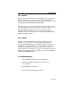
MAKING NETWORK CONNECTIONS 3.4 CONNECTING TO AN EXTERNAL TRANSCEIVER 3.4.1 AUI Connector (AUI Ports) 1 2 3 4 1. Wire Fault/Attachment LED 2. AUI Port 3. AUI Connector 4. Screws (2) Figure 3-5. Connecting an AUI Cable Any adapter with an AUI Port can be connected to the network via a transceiver and an AUI cable. The AUI port should have been selected during the installation procedure.
MAKING NETWORK CONNECTIONS 3.4.2 AUI Interface Type: Pin 1 2 3 4 5 6 7 8 15 position D type receptacle Logic Ground Collision + TX + Logic Ground RX + Logic Ground No Connection Logic Ground Pin 9 10 11 12 13 14 15 Shell Collision TX Logic Ground RX Power (+12 Vdc) Logic Ground No Connection Protective Ground 3.4.3 AUI Cable Requirements • Type - The AUI cable connecting the adapter to a transceiver must be Ethernet Version 1, Version 2, or IEEE 802.
ADDRESS/INTERRUPT TABLES APPENDIX A ADDRESS/INTERRUPT TABLES Table A-1.
ADDRESS/INTERRUPT TABLES Table A-2.
INDEX INDEX A G adapter features 1-2 10BASE-T port 1-2 connectivity 1-2 fiber optic ports 1-3 jabber protection 1-3 thin Ethernet port 1-2 adapter models 2-1 see table 2-1 2-1 E1100/E2100 series 2-2 installation 2-1 model number references 2-2 preparing the E1100 for installation 2-3 preparing the E2100 for installation 2-4 address/interrupt tables A-1 see table A-1 A-1 see table A-2 A-2 ADF file copying 2-14 getting help 2-16 E external transceiver 3-9 AUI cable requirements 3-10 AUI connector (AUI po
INDEX N network software loading 2-14 R related manuals 1-5 S see table A-2 A-2 setting the I/O base address jumper 2-5 software 1-5 software check list 2-15 specifications 2-18 dimensions 2-18 environmental 2-18 power requirements 2-18 safety 2-18 statistics 1-5 T thin-net segment connecting to 3-4 troubleshooting check list for adapters 2-15 Index-2