
Ethernet Network Adapter Installation Guide


Page 3-2
MAKING NETWORK CONNECTIONS
R
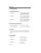
J-45 Port
RJ-45 Connector
12345678
Figure 3-2. RJ-45 Connector
RJ-45 Connections
Type: RJ-45 connector
Pin 1 TX+ Pin 5 No Connection
2 TX- 6 RX-
3 RX+ 7 No Connection
4 No Connection 8 No Connection
• Connect the twisted pair segment (4, Fig. 3-1) by inserting
the RJ-45 connector (3) into the adapter’s RJ-45 port (2).
• Check that the Link LED on the adapter is lit. The Link
LED may not light until data has been transmitted out the
10BASE-T port.
If you know the adapter has attempted to transmit data and the
LED is not lit, check the items listed here:
• Verify that the power is on for the PC.
• Check that the 10BASE-T device at the other end of the
twisted pair segment is powered up.
• Verify that the RJ-45 connector on the twisted pair segment
has the proper pinouts (see Figure 3-2, above).