
Setup guide


INTRODUCTION
Page 1-7
Any two matching power supply modules (i.e., two M8PSMs, two
M8PSM-Es, or two M8PSM-EDCs) will use a current sharing scheme
such that each power supply provides 50% of the required load (
±
5%,
5V output only) under all load conditions; if you have one M8PSM and
one M8PSM-E installed, the M8PSM-E will supply 60% of the
required power, and the M8PSM will supply the remaining 40%.
Note that, if you have an M8PSM and an M8PSM-E installed in the
same chassis, the redundancy LED on the M8PSM-E will not function.
Note, too, that you cannot mix AC (M8PSM or M8PSM-E) and DC
(M8PSM-EDC) power supplies in the same hub.
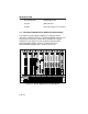
Hot Swapping
You have the option to “hot swap” power supply modules in the
M8FNB. This allows you to remove or insert power supplies without
powering down the M8FNB.
Internal Power Supply Cooling
The M8PSM-E and -EDC enhanced power supplies have two fans built
directly into the unit to provide additional cooling; red and green FAN
LEDs on the power supply’s front panel indicate whether all fans are
operational (green) or one or more has failed (red).
Power Level Indicator
The M8PSM-E and -EDC also include an 11-segment LED to indicate
the level of power currently being used by the chassis. Each
illuminated segment represents 10% of the maximum output; the
eleventh segment, when lit, indicates an overload condition. Note that,
if any one power supply is providing more than 50% of its available
power, there is no power supply redundancy available in the chassis.
The power requirements of some FDDI MIM
configurations require dual power supplies. Consult
the
appropriate manuals for details.
NOTE