
Setup guide

INSTALLATION REQUIREMENTS AND SPECIFICATIONS
Page 2-11
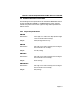
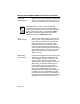
Fan A green LED indicates that all fans inside the
(E-series only) M8PSM-E or -EDC module are operating
properly; a red LED indicates that one or more
has failed.
Disable If this red LED is illuminated, the power
(E-series only) supply has been disabled remotely.
Power Level When illuminated, each of the first ten
(E-series only) segments of this LED indicates that 10% of
total power output is being used; the eleventh
segment, when illuminated, indicates a power
overload. Note that, in a redundant system,
segments 5-9 will illuminate yellow to warn of
loss of redundancy.
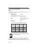
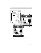
Fan Tray LED This LED is green when all the fans are
(Chassis) operating properly; it turns red when any fan
slows to half speed or less, and signals the
management/repeater module that there is a
fan tray problem. Note that this LED will also
turn red when the fan tray board’s logic has
failed due to a blown fuse; in this case, all fans
may still be operating.
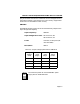
Even if neither LED is lit, redundancy is still available
if neither power supply is operating at more than 50
%
output. This is true even when one M8PSM and one
M8PSM-E are installed in the same chassis.
NOTE
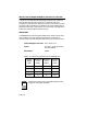
When the M8FNB is first powered up, this LED will be
red briefly until the fans are operating at the proper
speed. Also, don’t confuse this fan tray LED (located
on
the front of the fan tray installed at the bottom of th
e
chassis) with the Fan LED on the front panel of the
M8PSM-E and -EDC. This fan tray LED indicates t
he
operating status of the fans in the MMAC chassis; th
e
Fan LED on the M8PSM-E and -EDC indicates the
status of the fans inside the power supply itself.
NOTE