
Setup guide


MMAC-M8FNB SETUP
Page 3-8
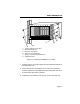
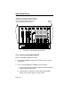
4. Slide the power supply into the appropriate slot of the
MMAC-M8FNB as follows:
a. Hold the module by the two handles on its front panel.
b. Align the power supply module with the slotted paths on the
top and bottom of the opening.
c. Ensuring that the power supply is inserted into the slotted
paths, carefully slide the module forward until the module is
connected to the backplane. Do not force the module into place!
If you encounter significant resistance, remove the power
supply and reinsert it.
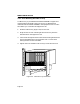
5. Use as screwdriver to tighten the knurled knobs and secure the
power supply module to the chassis.
6. If you are installing an additional power supply module, repeat
steps 3 - 5.
After you have finished installing the power supply module(s), the
MMAC-M8FNB is ready to be powered up; however, we recommend
that you first install the repeater/management module and the MIM
or MIMs, as well as the security bars. Refer to the applicable module
manuals for more information about MIM installation; see below for
security bar installation and power-up instructions.
When properly installed, the face of the M8PSM power
supply module will be flush with the rear panel of th
e
MMAC chassis; the face of the M8PSM-E or -EDC,
however, will extend about 3” out from the rear pane
l.
NOTE
One M8PSM and one M8PSM-E can be combined in a
single chassis, without loss of functionality; however
,
the Redundancy LEDs on the M8PSM-E will not
operate. See Chapter 2 for more details. Note, too, th
at
you cannot install an M8PSM-EDC in the same chas
sis
as either of the AC power modules.
NOTE