
Setup guide


MMAC-M8FNB SETUP
Page 3-10
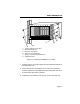
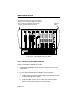
Figure 3-5. Installing the Security Bars
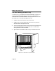
3.2.6 Powering Up the MMAC-M8FNB
Power up the MMAC-M8FNB as follows:
1. If the MMAC-M8FNB will not be rack mounted, place it on the
selected site.
2. For any installed M8PSM or M8PSM-E power supplies:
a. Plug a power cord into the power receptacle located on the front
of each installed power supply.
b. Plug the power cord(s) into an outlet and move the power
switch on each power supply to the on position.
Install the security bars over the knurled
knobs on the modules; align the screws in
the security bars with the holes in the
chassis as indicated, and secure.
Chassis
holes
AUI POK
26
15
2
3
4
5
6
7
8
9
10
11
12
13
R
C
V
L
N
K
R
C
V
L
N
K
TPRMIM-36
SN
ETHERNET
BC
CLN CLN
15
16
17
18
19
20
21
22
23
24
25
26
14 1
13
2
10BASE-T
ETHERNET
AUI POK
26
15
2
3
4
5
6
7
8
9
10
11
12
13
R
C
V
L
N
K
R
C
V
L
N
K
TPRMIM-36
SN
ETHERNET
BC
CLN CLN
15
16
17
18
19
20
21
22
23
24
25
26
14 1
13
2
10BASE-T
ETHERNET
ETHERNET
AUI POK
26
15
2
3
4
5
6
7
8
9
10
11
12
13
R
C
V
L
N
K
R
C
V
L
N
K
TPRMIM-36
SN
ETHERNET
BC
CLN CLN
15
16
17
18
19
20
21
22
23
24
25
26
14 1
13
2
10BASE-T
ETHERNET
B
Y
P
A
S
S
F
D
D
I
A
F
D
D
I
B
POWER
EFDMIM
SN
STAND
BY
FDDI
SYS
OK
F
D
D
I
M
M
A
C
TX
RX
WRAP
TOKISD
TX
RX
COL
POK
4
3
2
1
ON NET
LINK
C
O
N
S
O
L
E
16MB
TRMIM-4A
SN
MGMT
ACTIVE UTP
TOKEN RING
ERR
TX
RX
R
I
N
G
I
N
1
X
2
X
3
X
4
X
6
X
5
X
TX
RX
R
I
N
G
O
U
T
7
X
8
X
9
X
10
X
12
X
11
X
RI RO
CRS16
WFLT
WRAP
FO
FLNK
LNK
PEN
TRMIM-22A
SN
ACTIVE UTP
TOKEN RING
1
X
2
X
3
X
4
X
6
X
5
X
7
X
8
X
9
X
10
X
12
X
11
X
LNK
PEN
16MB
MGMT
ERR
ACTIVE UTP
TOKEN RING
1
X
2
X
3
X
4
X
6
X
5
X
7
X
8
X
9
X
10
X
12
X
11
X
LNK
PEN
16MB
MGMT
ERR
TRMIM-22A
SN
MMAC-M8FNB
The Complete Networking Solution™
Multi Media Access Center
EMME
SN
RESET
ON PWR
M
O
D
E
M
C
O
N
S
O
L
E
BOK
STBYA
STBYB
RCVA
RCVB
RCVC
RCVD
ERR
STBYC
STBYD
CLNA
CLNB
CLNC
CLND
A
U
I
1
A
U
I
2
ON PWR