
EMM-E6 Ethernet User's Guide


EMM-E6 QUICK REFERENCE CARD
EMM-E6 QUICK REFERENCE CARD
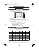
• Slide the EMM-E6 into the first and second slots of the MMAC chassis (as
shown below).
• Secure the module by tightening the knurled knobs at the top and bottom of
the module.
• Power on the MMAC chassis. Monitor the state of the CPU LED.
• The CPU LED will flash, indicating the EMM-E6 is in boot state. During this
period, which may last up to 5 minutes, the STBY LEDs will blink to indicate
the module’s boot state.
• Fully operational EMM-E6 should display the following LED states:
- CPU LED flashing, indicating normal operation.
- STBY LEDs lit or unlit, depending on the results of
spanning tree operation.
- Appropriate BRIM/EPIM LEDs lit.
- ON LED lit for the active Channel D EPIM.
Use the following setup parameters for a VT Terminal or Terminal Emulation
package to connect to Local Management functions.
Columns: 80 Columns Controls:
Interpret
Controls
Autowrap: No Autowrap
Scroll: Jump Scroll Text Cursor: Cursor Cursor Style: Underline
Mode: VT300, 7 Bit ID Number:
VT320 or
VT100
Cursor Keys: Normal
Transmit: 9600 Receive: 9600 XOFF: XOFF at 64
Bits: 8 Bits Parity: No Parity Stop Bit: 1 Stop Bit
Local Echo:
No Local
Echo
Port: DEC-423
Auto
Answerback:
No Auto
Answerback
Keys:
Typewriter
Keys
Margin Bell: Margin Bell
Warning
Bell:
Warning Bell
EMM-E6
INSTALLATION
TERMINAL SETUP
CH1Book Page 6 Wednesday, March 20, 1996 7:48 AM