
EMM-E6 Ethernet User's Guide


CHAPTER 2: REQUIREMENTS / CONFIGURATIONS
2-14 EMM-E6 User’s Guide
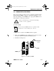
2.5.5 The EMM-E6 and BRIMs
The example in Figure 2-5 illustrates just one possible EMM-E6 and
BRIM configuration. The EMM-E6/BRIM combination provides various
connection possibilities, depending on the BRIM(s) you use. Refer to
individual BRIM manuals and/or Cabletron Systems’ Router Services
documentation to better understand the capabilities of each device.
Figure 2-5. The EMM-E6 and BRIMs
TPRMIM-33
CXRMIMFORMIM-22FORMIM-22TPMIM-24
TPMIM-24
Channel A
Channel B Channel C
EMM-E6
E
BRIM-FD2
TWR WRP
RCVXMT
LNK
Channel D
FDDI Backbone
Redundant
Connectivity
Ethernet
Backbone
EPIM-A
PWR
EPIM-A
PWR
CH1Book Page 14 Wednesday, March 20, 1996 7:48 AM