
EMM-E6 Ethernet User's Guide


SETTING MODE SWITCHES
EMM-E6 User’s Guide 3-3
3.2 SETTING MODE SWITCHES
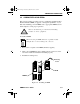
The bank of dip switches located at the top of the EMM-E6 (Figure 3-1)
are set to their default positions prior to shipping. Check these switches to
ensure that they are in the correct position for normal EMM-E6 operation.
Figure 3-1. EMM-E6 Mode Switches
ON
1 2 3 4 5 6 7 8
On
Off
Switches
EMM-E6
The potential for electric shock is present inside the MMAC
chassis when power is applied. Do not adjust switch settings
when the EMM-E6 is within a powered MMAC enclosure.
Failure to comply could result in personal injury and/or
equipment damage.
CH1Book Page 3 Wednesday, March 20, 1996 7:48 AM