MMAC-Plus™ 9F206-02 FDDI Repeater MicroLAN™ Module User’s Guide
Notice Notice Cabletron Systems reserves the right to make changes in specifications and other information contained in this document without prior notice. The reader should in all cases consult Cabletron Systems to determine whether any such changes have been made. The hardware, firmware, or software described in this manual is subject to change without notice.
Notice FCC Notice This device complies with Part 15 of the FCC rules. Operation is subject to the following two conditions: (1) this device may not cause harmful interference, and (2) this device must accept any interference received, including interference that may cause undesired operation. NOTE: This equipment has been tested and found to comply with the limits for a Class A digital device, pursuant to Part 15 of the FCC rules.
Notice Safety Information CLASS 1 LASER TRANSCEIVERS The FPIM-05 and FPIM-07 are Class 1 Laser Products CLASS 1 LASER PRODUCT The FPIM-05 and FPIM-07 use Class 1 Laser transceivers. Read the following safety information before installing or operating these adapters. The Class 1 laser transceivers use an optical feedback loop to maintain Class 1 operation limits. This control loop eliminates the need for maintenance checks or adjustments. The output is factory set, and does not allow any user adjustment.
Notice Safety Information CLASS 1 LASER TRANSCEIVERS Laser Radiation and Connectors When the connector is in place, all laser radiation remains within the fiber. The maximum amount of radiant power exiting the fiber (under normal conditions) is -12.6 dBm or 55 x 10-6 watts. Removing the optical connector from the transceiver allows laser radiation to emit directly from the optical port. The maximum radiance from the optical port (under worst case conditions) is 0.8 W cm-2 or 8 x 10³ W m2 sr-1.
Contents Chapter 1 Introduction Features........................................................................................................................... 1-1 Related Manuals............................................................................................................ 1-4 Getting Help .................................................................................................................. 1-4 Chapter 2 Installing the MicroLAN Module Unpacking the Module...................
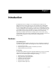
Chapter 1 Introduction The 9F206-02 (as shown in Figure 1-1) is an FDDI repeater module for the MMAC-Plus that provides external access to the Flexible Network Bus (FNB) backplane via two sets of FDDI-compliant A/B ports. This allows the FNB to traverse multiple MMAC-Plus systems, or connect to any ASNI FDDI-compliant device in an FDDI network.
Introduction LANVIEW LEDs The 9F206-02 uses LANVIEW: the Cabletron Systems built-in visual diagnostic and status monitoring system for at-a-glance diagnosis of the network. With LANVIEW LEDs, you can quickly identify the device, port, and physical layer status. Hot Swapping The 9F206-02 can be installed or removed from the chassis while the MMAC-Plus is powered up without affecting the operation of the rest of the system.
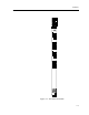
Features FDDI 9F206-02 SMB CPU 1 2 A F D D I 1 B A F D D I 2 B MMAC PLUS Figure 1-1.
Introduction Related Manuals The manuals listed below should be used to supplement the procedures and technical data contained in this manual.
Chapter 2 Installing the MicroLAN Module This module uses FPIMs for the front panel connections. They are not shipped with the module and must be purchased separately. For more information on FPIMs see Appendix A. Unpacking the Module 1. Carefully remove the module from the shipping box. (Save the box and packing materials in the event the module must be reshipped.) 2. Remove the module from the plastic bag. Observe all precautions to prevent damage from Electrostatic Discharge (ESD). 3.
Installing the MicroLAN Module Figure 2-1.
User-Accessible Components User-Accessible Components Figure 2-2 shows the various components that are accessible to the user. These consist of an eight position dip switch (explained in the next section) and sockets for replaceable PROMs. These will be used for future upgrades. Instructions for installing the components will be supplied with the upgrade kit. SMB-1 PROM Boot PROM DIP Switch Figure 2-2.
Installing the MicroLAN Module Setting the Module Card DIP Switch An eight switch DIP switch is located on the module card as shown in Figure 2-2 and Figure 2-3. The functions of the switches are listed in Table 2-1. 1 2 3 4 5 6 7 8 Figure 2-3.
Setting the Module Card DIP Switch Table 2-1. Function of DIP Switch Switch Function Description On Off Factory Default 1 None Not Used. N/A N/A N/A 2 None Not Used. N/A N/A N/A 3 FNB-1 External Ring Specifies which ring is externalized for FNB-1. Primary Secondary Primary 4 FNB-2 External Ring Specifies which ring is externalized for FNB-2. Primary Secondary Primary 5 FNB-1 Status The status of the FNB-1.
Installing the MicroLAN Module Installing the Module into the MMAC-Plus Chassis MMAC-Plus MicroLAN Modules can be installed in any of the 14 slots that are available. To install, follow the steps below: 2-6 1. Switch off the power supplies and remove all power from the MMAC-Plus chassis. 2. Remove the blank panels, covering the slots that the module is being mounted in. All other slots must be covered, if modules are not being installed, to ensure proper airflow and cooling. 3.
Installing the Module into the MMAC-Plus Chassis 7 FLNK 8 FLNK FLNK 10 RX FLNK INS TX 11 RX FLNK INS TX 12 RX Jack for ESD wrist strap Metal Back-Panel Circuit Card Card Guides Warning: Ensure that the circuit card is between the card guides. Lock down the top and bottom plastic tabs at the same time, applying even pressure. Figure 2-4.
Installing the MicroLAN Module The Reset Switch The Reset switch is located on the front panel, under the top plastic tab as shown in Figure 2-5. It serves two functions: • • Pressing the Reset switch twice within three seconds causes the main CPU to reset. Pressing and holding the switch on for three or more seconds causes the module to shutdown. Pressing and holding again for three seconds restarts the module. Reset Switch SMB CPU Figure 2-5.
Chapter 3 Operation The 9F206-02 module, as shown in Figure 3-1, provides two repeater ports that extend the FNB bus outside the MMAC-Plus chassis. No bridging or routing is done in this module. Each port connects to both rings (Primary and Secondary) on each FNB (FNB-1 and FNB-2). DC/DC Converter SMB-1 System Diagnostic Controller A FDDI-1 Driver/Receiver FNB Interface B FNB -1 and FNB -2 Front Panel Connections A Driver/Receiver FNB Interface FDDI-2 B Figure 3-1.
Operation System Management Bus There are two management channels within the MMAC-Plus system: the SMB-1 and the SMB-10. These buses provide out-of-band management and inter-module management communication. The 9F206-02 uses only the SMB-1 bus. The SMB-1 is a 1 Mbps management bus located within the MMAC-Plus. This bus is utilized by all diagnostic controllers in the system including connectivity modules, power supply modules and the environmental module.
CPU CPU The CPU handles all low level SMT functions as well as module configuration requests. The CPU is also responsible for all environmental, power and system level communication between modules in the MMAC-Plus chassis.
Chapter 4 LANVIEW LEDs The front panel LANVIEW LEDs indicate the status of the module and may be used as an aid in troubleshooting. Shown in Figure 4-1 are the LANVIEW LEDs of the 9F206-02 module. FDDI 9F206-02 SMB and CPU SMB CPU FDDI Port Status 1 2 A Figure 4-1.
LANVIEW LEDs The functions of the System Management Bus (SMB) and CPU LEDs are listed in Table 4-1. Table 4-1. SMB and CPU LEDs State LED Color Description Green Functional Fully operational. Yellow (Flashing) Crippled Not fully operational (i.e., one bad port). Yellow/Green Booting Blinks yellow and green while booting. Red Reset Normal power-up reset. Red (Flashing) Failed Fatal error has occurred. Off Power off Module powered off.
LANVIEW LEDs The functions of the FDDI Port Status LEDs are listed in Table 4-2. Table 4-2. FDDI Port Status LEDs STATE LED Color Green Link, Active, Port Enabled Yellow Link, Not Active, Port Enabled Red Not Link, Port Disabled Red (Flashing) Link, Port Disabled Off No Link, Not Active, Port Enabled The functions of the FDDI Status LEDs are listed in Table 4-3. Table 4-3.
Chapter 5 General Specifications Safety ! CAUTION It is the responsibility of the person who sells the system to which the module will be a part to ensure that the total system meets allowed limits of conducted and radiated emissions. This equipment meets the following safety requirements: • • • • • • • • UL 1950 CSA C22.2 No.
General Specifications Physical Dimensions: 35.0 D x 44.0 H x 3.0 W centimeters (13.8 D x 17.4 H x 1.2 W inches) Weight: 5-2 Unit: 1.36 kg. (3 lb) Shipping: 1.81 kg.
Appendix A FPIM Specifications This MMAC-Plus module uses Fiber Port Interface Modules (FPIM) to provide front panel cable connections. The FPIMs are user-installable. See the section titled Installing an FPIM on page 2-1. FPIM-00 and FPIM-01 The FPIM-00 and FPIM-01 provide a multimode fiber connection. The FPIM-00 uses a MIC style connector and the FPIM-01 uses an SC type connector. The specifications for both devices are listed in Table A-1. Table A-1.
FPIM Specifications Transmitter power parameters are listed in Table A-2. Table A-2. Transmitter Power Parameters Parameter Typical Value Worst Case Worst Case Budget Typical Budget 50/125 µm fiber -13.0 dBm -15.0 dBm 13.0 dB 17.5 dB 62.5/125 µm fiber -10.0 dBm -12.0 dBm 16.0 dB 20.5 dB 100/140 µm fiber -7.0 dBm -9.0 dBm 19.0 dB 23.5 dB Error Rate Better than 10-10 The link distance is up to 2 kilometers on the multimode fiber-optic cable as specified by ANSI MMF-PMD.
FPIM-05 and FPIM-07 FPIM-05 and FPIM-07 The FPIM-05 and FPIM-07 provide a Single-mode fiber connection. The FPIM-05 uses a MIC style connector and the FPIM-07 uses an SC type connector. The specifications for both devices are listed in Table A-4. Table A-4. FPIM-05 and FPIM-07 Specifications Parameter Typical Minimum Maximum Transmitter Peak Wave Length 1300 nm 1270 nm 1330 nm Spectral Width 60 nm - 100 nm Rise Time 3.0 nsec 2.7 nsec 5.0 nsec Fall Time 2.5 nsec 2.2 nsec 5.