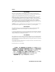
FAST NETWORK 100 USER GUIDE FN100-8 Port Status Mode TX Act 100 Select Ready Reset RX Col Usr Pwr TX RX NMS Port Link Status Link Status 1 1X 2X 3X 4X 5X 6X 8X 7X 1 2 3 4 5 6 7 8 FN100-8FX Port Status Mode TX Act 100 Select Ready Reset RX Col Usr TX RX TX RX TX RX TX RX TX RX TX RX TX RX Pwr TX RX NMS Port Link Status 1 2 3 5 4 6 1 2 3 4 5 6 7 8 8 7 TX RX 9 10 11 12 13 14 15 16 Link Status Link Status 9 9X 10X 11X 12X 13X 14X FN100-16 16X 15X Port
NOTICE Cabletron Systems reserves the right to make changes in specifications and other information contained in this document without prior notice. The reader should in all cases consult Cabletron Systems to determine whether any such changes have been made. The hardware, firmware, or software described in this manual is subject to change without notice.
Notice FCC NOTICE This device complies with Part 15 of the FCC rules. Operation is subject to the following two conditions: (1) this device may not cause harmful interference, and (2) this device must accept any interference received, including interference that may cause undesired operation. NOTE: This equipment has been tested and found to comply with the limits for a Class A digital device, pursuant to Part 15 of the FCC rules.
Notice CABLETRON SYSTEMS, INC. PROGRAM LICENSE AGREEMENT IMPORTANT: Before utilizing this product, carefully read this License Agreement. This document is an agreement between you, the end user, and Cabletron Systems, Inc. (“Cabletron”) that sets forth your rights and obligations with respect to the Cabletron software program (the “Program”) contained in this package. The Program may be contained in firmware, chips or other media.
Notice UNITED STATES GOVERNMENT RESTRICTED RIGHTS The enclosed product (a) was developed solely at private expense; (b) contains “restricted computer software” submitted with restricted rights in accordance with Section 52227-19 (a) through (d) of the Commercial Computer Software - Restricted Rights Clause and its successors, and (c) in all respects is proprietary data belonging to Cabletron and/or its suppliers.
CONTENTS CHAPTER 1 INTRODUCTION 1.1 Getting Help................................................................................. 1-2 1.2 Document Conventions ............................................................... 1-2 1.3 Related Documentation ............................................................... 1-3 1.4 Overview...................................................................................... 1-4 1.4.1 OSI Compliance..............................................................
Contents 2.5 2.6 2.7 Local Console Manager Overview ...............................................2-6 Command Syntax Conventions ...................................................2-6 2.6.1 Basic LCM Commands....................................................2-7 2.6.1.1 help .................................................................2-8 2.6.1.2 erase ...............................................................2-8 2.6.1.3 exit ..................................................................
Contents CHAPTER 4 MONITORING AND MANAGING THE FN100 4.1 FN100 Management Tools .......................................................... 4-1 4.2 FN100 Statistics .......................................................................... 4-2 4.2.1 Gathering Statistics......................................................... 4-2 4.2.2 System Statistics ............................................................ 4-3 4.2.3 Ethernet Port Statistics ................................................... 4-3 4.2.
Contents APPENDIX A TECHNICAL SPECIFICATIONS A.1 FN100 Specifications .................................................................. A-1 A.2 Types/Connectors ....................................................................... A-3 A.3 Cable Specifications ................................................................... A-3 A.3.1 10BASE-T Cable Specifications ..................................... A-3 A.3.2 100BASE-TX Cable Specifications................................. A-4 A.3.
CHAPTER 1 INTRODUCTION This manual is for system administrators responsible for installing, configuring, monitoring, and maintaining the Cabletron Systems Fast Network 100 (FN100) switch. You should have a familiarity with networking concepts and principles. In addition, a basic understanding of Simple Network Management Protocol (SNMP) is helpful. This manual provides instructions for using the FN100’s internal Local Console Manager (LCM) to set basic configuration parameters.
Chapter 1: Introduction • Appendix A, Technical Specifications, provides the FN100 specifications and basic 10BASE-T and 100BASE-TX cabling pin assignments. • Appendix B, Glossary, provides a glossary of terms both specific to the FN100 and common to the networking field. 1.
Related Documentation NOTE TIP ! Note symbol. Calls the reader’s attention to any item of information that may be of special importance. Tip symbol. Conveys helpful hints concerning procedures or actions. Caution symbol. Contains information essential to avoid damage to the equipment. CAUTION Warning symbol. Warns against an action that could result in equipment damage, personal injury or death. 1.
Chapter 1: Introduction (MM) fiber. The FN100 is available in the four configurations shown below.
Overview The FN100 features the following: • Supports 10BASE-T, 100BASE-TX, and 100BASE-FX standards. • Supports IEEE 802.3u Auto-Negotiation for 10BASE-T and 100BASE-TX connections. • Provides full store and forward switching functionality. • Supports trunking for combining up to 8 links for a total bandwidth of 800 Mbps. • Lets you define virtual workgroups to optimize network traffic. • Allows you to configure the FN100 into four virtual switches. • Supports 48-bit IEEE 802 MAC addressing.
Chapter 1: Introduction To dynamically arbitrate between 10 Mbps and 100 Mbps on each port, the FN100 employs IEEE 802.3u Auto-Negotiation. Auto-Negotiation allows each 10BASE-T/100BASE-TX port on the FN100 to self-configure to 100 Mbps when the device on the other end of the wire is also capable of self-configuration to 100 Mbps. This is performed automatically via information exchanged between devices sharing the same link without management intervention.
FN100 Architecture 1.5 FN100 ARCHITECTURE The FN100 is based on an architecture that utilizes a high speed switch engine coupled with an AMD 29200 RISC processor for management functions. This architecture provides an efficient mix of optimal performance and intelligence.
Chapter 1: Introduction 1.5.2 Spanning Tree Algorithm The FN100 supports the IEEE 802.1d Spanning Tree algorithm. The Spanning Tree algorithm converts multiple LANs into a “spanning tree” of networks that prevents bridging loops. This standard defines a logical (not physical) network configuration consisting of one extended LAN without active duplicate paths between spanning tree bridges. The FN100, along with other IEEE 802.
FN100 Architecture The FN100 learns addresses from all packets, including data transmissions and “keep alive” packets (packets sent by an idle station to let other stations know it is present and functional). When devices are added to the network, removed from it, or relocated, you do not have to reconfigure the FN100. The FN100 automatically learns new device addresses, and recognizes when a previously used address is missing, or when a device has been moved to a new LAN segment.
Chapter 1: Introduction 1.6 FN100 APPLICATIONS The FN100 provides the network designer with complete flexibility and has many applications including: • Server farms • High-performance workgroups • Backbones 1.6.1 Server Farms FN100 Fast Ethernet Server Farm Figure 1-6 Using the FN100 to Create Server Farms As shown in Figure 1-6, the FN100 replaces conventional Ethernet 10BASE-T hubs and switches to provide each fileserver a dedicated 100 Mbps pipe.
FN100 Applications 1.6.2 High-Performance Workgroups FN100 FN100 Figure 1-7 Creating High-Performance Workgroups As workstation performance continues to grow, Fast Ethernet switching is the perfect choice for addressing the new bandwidth requirement. Providing the most cost-effective bandwidth compared to other high-speed technologies, the FN100 provides dedicated 100 Mbps to each workstation.
Chapter 1: Introduction 1.6.3 Backbones Studies indicate that backbone congestion is the number one issue facing most networks. The FN100 reduces congestion by increasing the overall aggregate bandwidth between existing routers, switches or hubs. A Fast Ethernet backbone consisting of one or more FN100 switches that consolidate the traffic needed to traverse to the backbone is shown in Figure 1-8.
FN100 Configurations 1.7.1 Trunking Configurations If your network configuration requires you to connect two or more FN100 switches together, but the applications you are running over the network require more than 100 Mbps of bandwidth per connection, you can use the built-in trunking feature to increase bandwidth up to 800 Mbps, without installing additional hardware on your network. The FN100 supports up to 8 trunk groups with 2 to 8 ports per trunk group.
Chapter 1: Introduction NOTE In some wiring closets, it may be easier to connect two FN100 switches via an Ethernet concentrator. However, you must make sure that there are no other devices connected to the Ethernet concentrator. 1.7.1.1 Trunking Configuration Examples The FN100 allows multiple trunk groups with up to eight ports each to be connected between the FN100 and other network devices. This capability provides a scalable dedicated bandwidth of up to 800 Mbps.
FN100 Configurations Servers 100BASE-TX Cables FN100 100 Mbps 100 Mbps ATX Trunk Lines Network Management Station 100 Mbps 100 Mbps 100BASE-TX Cables FN100 WAN Router Workgroup Hub Figure 1-11 FN100 Trunking Configuration Example #2 1.7.2 Virtual Switch Configurations The FN100 can be configured as a collection of virtual switches. Virtual switches provide increased bandwidth, enhanced security, and other advantages gained by having multiple switches operating in your network.
Chapter 1: Introduction 1.7.2.1 Virtual Switch Configuration Examples Figure 1-12 shows a 16-port FN100 configured as two virtual switches, each attached to a separate non-Cabletron Systems device.
FN100 Configurations 1.7.3 Workgroups The FN100 allows you to define ports for logical groups of associated hosts to create workgroups. Workgroups provide an efficient flow of traffic across an Ethernet network by enabling you to limit broadcasts to logical domains within the network. The FN100 recognizes Workgroup destinations and routes broadcast packets directly to hosts within the workgroup, eliminating the need to perform a general broadcast across each segment of the network to find host addresses.
Chapter 1: Introduction Page 1-18 Fast Network 100 User Guide
CHAPTER 2 UNPACKING AND INSTALLING THE FN100 Carefully unpack the FN100 from the shipping carton and inspect it for possible damage. If any damage is evident, contact Cabletron Systems.
Chapter 2: Unpacking and Installing the FN100 .
Installing the FN100 2.3.2 Rack-Mounting the FN100 The table below describes some general considerations you should be aware of before mounting the FN100 in a rack assembly. Table 2-1 General Considerations for Mounting the FN100 Consideration Discussion Temperature Since the temperature within a rack assembly may be higher than the ambient room temperature, make sure the rack-environment temperature is within the Operating Temperature range specified in Appendix A.
Chapter 2: Unpacking and Installing the FN100 3. Secure the FN100 with the rack-mount fasteners by inserting and securing a fastener through each of the four slots in the rack-mount brackets, as shown in Figure 2-3.
Connecting the Local Console Manager 5. After several more seconds, the Ready LED will stay on, indicating that the power-up diagnostics sequence is complete. In addition, the Port Link LEDs will turn on for those ports with good links and the Segment Status LEDs will turn on (or flash) when the selected status condition is present. NOTE If the Ready LED does not stay on, contact Cabletron Systems Technical Support. Refer to Chapter 1, Section 1.1, Getting Help. 2.
Chapter 2: Unpacking and Installing the FN100 2.5 LOCAL CONSOLE MANAGER OVERVIEW The Local Console Manager (LCM) is a command-line interface built into the FN100 that enables you to monitor, manage, and configure the FN100 through the out-of-band RS232C connection on the front panel attached to any non-intelligent terminal. You can also use a Cabletron Systems Network Management System, or a standard SNMP-based Network Management System, to manage the FN100.
Command Syntax Conventions • A previous command can be repeated by typing !!. • MAC addresses are displayed in little-endian Ethernet bit order, with each octet separated by a colon. For example: FN100 > address 00:40:27:04:1a:0f • Information that you need to enter with an LCM command is enclosed in brackets < >. For example, you must enter a port number and an IP address to execute the ipaddr command: FN100 > ipaddr 6 192.138.217.
Chapter 2: Unpacking and Installing the FN100 2.6.1.1 help Use the help command to display the menu of available commands. Help can also be displayed by typing a question mark (?). The output from the help command is displayed below.
Connecting the FN100 to the Network 2.7 CONNECTING THE FN100 TO THE NETWORK Installations vary depending on existing wiring, application objectives, and other considerations. Be sure to have your current network topology map available or contact your network administrator. You can connect network devices to the FN100 via a 10BASE-T, 100BASE-TX, or 100BASE-FX cable directly, or via a punch-down block or patch panel located in a wiring closet. Individual devices are then connected to the FN100. 2.7.
Chapter 2: Unpacking and Installing the FN100 2.7.3 Wiring Considerations Each port on the FN100 has built-in internal crossovers. If the network device you are connecting to the FN100 has an internal crossover design, use an internal crossover cable. If the device you are connecting has a straight-through design, use a straight-through cable. For more information about straight-through and crossover wiring considerations, refer to Appendix A.
CHAPTER 3 CONFIGURING THE FN100 The FN100 does not require any additional configuration to operate as a standard, transparent switch. However, if you want to use any of the FN100 advanced functions, such as workgroups, you must first assign an IP (Internet Protocol) address to any of the ports on the FN100 that you use to communicate with a Simple Network Management Protocol (SNMP) manager. To initially assign an IP address, you can use the Local Console Manager (LCM). For more information, see Section 3.
Chapter 3: Configuring the FN100 • Assigning a community name NOTE You can use the LCM erase command to erase all configuration information on the next system reset. If you are using a network management tool other than LCM, refer to its accompanying documentation. 3.1 ASSIGNING IP ADDRESSES IP addresses for each port must be unique. IP addresses are divided into classes based on what portion of the address is network or port information. The address classes are A, B, and C.
Assigning IP Addresses 3.1.1 Displaying IP Addresses Use the ipaddr command to display IP addresses, subnet masks, and MAC addresses of all ports on the FN100 you are configuring. LCM displays the current IP address table, for example: FN100 > ipaddr Port IP 1 2 3 4 5 6 7 8 Address 198.113.121.149 0.0.0.0 0.0.0.0 0.0.0.0 0.0.0.0 0.0.0.0 0.0.0.0 0.0.0.0 Address Mask 255.255.255.0 255.0.0.0 255.0.0.0 255.0.0.0 255.0.0.0 255.0.0.0 255.0.0.0 255.0.0.
Chapter 3: Configuring the FN100 NOTE When you change the subnet mask for a port, you must also enter the IP address for that port. Be sure to enter the port’s IP address correctly; whatever you enter becomes the IP address. 3.2 SETTING PORT SPEED Use the LCM speed command to select a bandwidth of 10 Mbps or 100 Mbps for each port. The options include: • auto - (default) Allows the FN100 to auto-detect the maximum bandwidth available for the port(s) based on the existing connection.
Enabling Bridging 3.3 ENABLING BRIDGING Use the LCM bridge command to set bridging options for a single port or a range of ports. The options include: • off • on (the default with BPDU enabled) • noBPDU BPDU (Bridge Protocol Data Unit) is a data unit transmitted as part of the IEEE 802.1d Spanning Tree protocol. The exchange of BPDUs allows bridges within a network to logically configure the network as a single spanning tree.
Chapter 3: Configuring the FN100 FN100 > bridge LCM responds with a list of all ports and the bridging function that is enabled.
Trunking 100 Mbps 100 Mbps FN100 A 100 Mbps 100 Mbps FN100 B 100 Mbps 100 Mbps FN100 C Trunk Group #1 Trunk Group #2 Figure 3-1 Trunk Groups To enable trunking for the example shown above, you would: 1. Connect the desired ports of the FN100 switches together using crossover cables. If Switch A is handling only a small number of users, the A to B Trunk Group could have just two ports per FN100.
Chapter 3: Configuring the FN100 standard 802.1D Spanning Tree state changes, treating each Trunk Group as a single 802.1D Spanning Tree port. 802.1D Spanning Tree takes about thirty seconds to resolve which FN100 ports are to become forwarding ports. As ports within a Trunk Group become forwarding ports, traffic within the Trunk Group is momentarily halted to guarantee the first-in, first-out ordering of the Ethernet packets. NOTE The Fast Network-to-Fast Network connections must be point-to-point.
Displaying Trunking Status The following conditions can be displayed: • Closed (or Oneway) — Trunking is enabled, and the Trunking Protocol is attempting to establish a trunk connection. • Heldown — Trunking is enabled, but the trunk connection was rejected. After a short time-out period, another attempt is automatically initiated to establish a good trunk connection. • Joined — Trunking is enabled, and the Trunking Protocol has established a good trunk connection. • Off — Trunking is not enabled.
Chapter 3: Configuring the FN100 The following conditions can be displayed in the Trunking State field: • Broken — Trunking is enabled, but the port in non-operational. • Closed (or Oneway) — Trunking is enabled, and the Trunking Protocol is attempting to establish a trunk connection. • Heldown — Trunking is enabled, but the trunk connection was rejected. After a short time-out period, another attempt is automatically initiated to establish a good trunk connection.
Defining and Deleting Virtual Switches 3.9.1 Displaying Virtual Switch Information Use the vswitch command to display all of the virtual switch configurations defined by the FN100. FN100 > vswitch LCM responds: Virtual Switch: Sw1: 1,2,3,4,5,6,7,8 Sw2: 9,10,11,12,13,14,15,16 Sw3: Sw4: Use the vswitch command to display information about a specific workgroup. For example: FN100 > vswitch sw1 LCM responds: Virtual Switch: Sw1: 1,2,3,4,5,6,7,8 3.9.
Chapter 3: Configuring the FN100 LCM responds: Virtual Switch: Sw1: 2,3,4,5,6,8 Use the vswitch remove command to remove ports from an existing virtual switch configuration. For example: FN100 > vswitch sw1 remove 2-4 LCM responds: Virtual Switch: Sw1: 5,6,8 3.10 DEFINING AND DELETING WORKGROUPS The FN100 allows you to define logical groups of associated hosts to create workgroups that provide a more efficient flow of traffic across your Ethernet network.
Defining and Deleting Workgroups Use the workgroup command to create or modify the port list for a specific workgroup. For example: FN100 > workgroup a 2-6 Figure 3-2 shows the FN100 with two defined workgroups (A and B). Workgroup A uses ports 1 through 3, and workgroup B uses ports 5 and 7.
Chapter 3: Configuring the FN100 LCM responds: Name: a Ports: 1, 2, 3, 11, 12 Type: All 2. To create workgroup B on ports 5, 7, 15: FN100 > workgroup B 5,7,15 LCM responds: Name: b Ports: 5, 7, 15 Type: All Port 11 has been assigned to a segment that includes hosts that belong to workgroup A and workgroup B. Port 12 connects workgroup A to the router and port 15 connects workgroup B to the router. 3.
Assigning a Community Name The localfilter command displays the current filtering option for all ports: FN100 > localfilter Usage: localfilter [PORT-RANGE [hardware | software]] Port 1 - Filtertype : Software Port 2 - Filtertype : Software Port 3 - Filtertype : Software Port 4 - Filtertype : Software Port 5 - Filtertype : Software Port 6 - Filtertype : Hardware Port 7 - Filtertype : Hardware Port 8 - Filtertype : Hardware The localfilter command displays settings for local traffic filtering for th
Chapter 3: Configuring the FN100 Use the community command to assign a community name. At the LCM prompt: 1. Type community 2. Enter the old community name. If one has not been assigned, you do not need to enter anything. LCM prompts you for the new community name. 3. Enter the new community name. LCM prompts you to verify the new community name by retyping it. 4. Retype the new community name. 3.13 CONFIGURING MULTICAST STORM PROTECTION The FN100 provides automatic protection against multicast storms.
Modifying MIB Variables The two Management Information Base (MIB) variables for configuring multicast storm protection are: • sfifTxStormCnt – specifies the maximum number of multicasts that can be broadcast within the given time. • sfiTxStormTime – specifies the period of time that the maximum number of multicasts can be broadcasted. Refer to the Fast Network 100 MIB Reference Guide for a complete listing and description of MIB variables. 3.
Chapter 3: Configuring the FN100 3.14.2 System Name The system name is a name assigned to the FN100 by the network administrator. By convention, the system name is the fully qualified domain name. (This name then becomes the LCM prompt.) sysName - {system 5} DisplayString (SIZE (0..255)) 3.14.3 System Location The system location identifies the physical location of the FN100. sysLocation - {system 6} DisplayString (SIZE (0..255)) 3.14.
Modifying MIB Variables 3.14.4.2 Get Password The get password variable (sfadminGetPass) must be set to the value of the community name used by the SNMP manager for performing get operations. A zero length password means that any community name is acceptable. sfadminGetPass - {sfadmin 3} DisplayString (SIZE (0..24)) 3.14.5 Aging Parameter Dynamic (learned) addresses are automatically deleted from the FN100 Bridge Address Table after a certain length of time.
Chapter 3: Configuring the FN100 Page 3-20 Fast Network 100 User Guide
CHAPTER 4 MONITORING AND MANAGING THE FN100 Monitoring the FN100 consists of collecting and analyzing statistics and system status information. You can use the Select button on the front panel of the FN100 to monitor segment status on any of the Ethernet ports. See Status and Activity Indicators in Chapter 5 for a description of the status options.
Chapter 4: Monitoring and Managing the FN100 example, Ethernet port statistics help you identify network devices that require high bandwidth, and therefore should be connected through a dedicated, rather than a shared, network connection. In addition, Ethernet port statistics help you identify a network device that is the source of numerous multicast packets due to a possible malfunction. 4.2.1 Gathering Statistics For purposes of network management, managed objects, such as the FN100, must be identified.
FN100 Statistics 4.2.3 Ethernet Port Statistics Ethernet statistics help you analyze network activity and utilization, and in some cases, indicate faulty equipment or cabling. For each Ethernet port connection on the FN100, the following statistics are available: • The number of packets received from the port.
Chapter 4: Monitoring and Managing the FN100 • The number of packets not transmitted to the LAN. The packets are broken down into the following categories: - Not sent due to congestion - Not sent due to multicast storm protection • The number of received Frame Check Sequence (FCS) errors detected. • The number of missed packets due to receive queue overflows. • The number of received packets with frame alignment errors.
Using LCM to Check FN100 Status • The number of SNMP PDUs received with an authentication failure. [snmpInBadCommunityUses] • The number of SNMP PDUs received with an ASN.1 parsing error while being decoded. [snmpInASNParseErrs] • The total number of MIB objects which have been successfully retrieved as a result of SNMP GetRequest or GetNext PDUs. [snmpInTotalReqVars] • The total number of MIB objects which have been successfully altered as a result of SNMP SetRequest PDUs.
Chapter 4: Monitoring and Managing the FN100 • Address display • Ipaddr • Ident These LCM commands are described in the sections that follow. 4.3.1 Displaying Status Use the status command to display the status of the FN100 and automatically page through the status of all of the Ethernet ports, pausing at each information screen. NOTE You can also use the status command to display status for individual Ethernet ports by typing status and specifying a port number.
Using LCM to Check FN100 Status Port 1 2 3 4 5 6 7 8 . . .
Chapter 4: Monitoring and Managing the FN100 You can continue to press the Return key to display status information for each individual port.
Using LCM to Check FN100 Status - BPDU (the MAC address to which all BPDUs are directed) - Reserved (the address reserved by 802.1d, but not yet assigned) - All LANs (the addresses reserved by 802.1d for network management) • Port number • Virtual switch number The display automatically pauses with each screen of information. Addresses are displayed in random order; for example, address 02:00:00:00:00:00 may appear after address 04:00:00:00:00:00.
Chapter 4: Monitoring and Managing the FN100 Use the address display command to display a range of addresses using a net mask. This is helpful when determining the status associated with stations containing the same make of Ethernet network interface cards.
Using LCM to Check FN100 Status LCM displays the current IP address table, for example: Port 1 2 3 4 5 6 7 8 IP Address 198.113.121.149 0.0.0.0 0.0.0.0 0.0.0.0 0.0.0.0 0.0.0.0 0.0.0.0 0.0.0.0 Address Mask 255.255.255.0 255.0.0.0 255.0.0.0 255.0.0.0 255.0.0.0 255.0.0.0 255.0.0.0 255.0.0.0 MAC Address 00:40:27:07:b6:f6 00:40:27:07:b6:f7 00:40:27:07:b6:f8 00:40:27:07:b6:f9 00:40:27:07:b6:fa 00:40:27:07:b6:fb 00:40:27:07:b6:fc 00:40:27:07:b6:fd For more detailed information, see Chapter 3, Section 3.
Chapter 4: Monitoring and Managing the FN100 4.4 USING LCM TO MANAGE THE FN100 You can use the Local Console Manager (LCM), any Cabletron Systems NMS, or a standard SNMP-based NMS to manage the FN100. For more information, see Section 4.1, FN100 Management Tools. LCM commands that enable you to manage the FN100 include: • Disable • Enable • Ipaddr • Community • Baud • Reboot 4.4.
Using LCM to Manage the FN100 ! CAUTION If you disable the port through which someone is remotely managing the FN100, that person will not be able to communicate with the FN100. Use the LCM address display command to find the port number you are using to manage the FN100. 4.4.2 Enabling a Port When you enable an Ethernet port that has been disabled, whatever bridging functions you had previously configured for that port are re-enabled.
Chapter 4: Monitoring and Managing the FN100 4.4.3 Changing a Subnet Mask You can optionally set the subnet mask for a port. A subnet mask is a 32-bit address mask used in IP to specify a particular subnet. If the subnet mask is omitted, the FN100 automatically uses the standard default, based on the port’s IP address class. (Class A address masks are 255.0.0.0, Class B address masks are 255.255.0.0, Class C address masks are 255.255.255.0.
Using LCM to Manage the FN100 3. Enter the new community name. LCM prompts you to verify the new community name by retyping it. 4. Retype the new community name. 4.4.5 Setting the Baud Rate You can set the baud rate for your LCM console connection. The options for baud rate include: • 1200 • 2400 • 4800 • 9600 • 19200 The default rate is 9600. NOTE Make sure that the baud rate you set matches the baud rate setting for the terminal you are using.
Chapter 4: Monitoring and Managing the FN100 4.4.6 Setting a Reboot Time Use the reboot command to enter the number of seconds the FN100 waits before rebooting. For example, to set the reboot time interval to 60 seconds: FN100 > reboot 60 LCM responds: System will be reset in 60 seconds.
CHAPTER 5 FN100 DIAGNOSTICS AND TROUBLESHOOTING The FN100 incorporates several built-in diagnostic and testing capabilities which are convenient to use and cause minimal or no disruption to the operational network. These capabilities are effective for isolating problems within the FN100 unit. Built-in diagnostic capabilities include system-wide power-up diagnostics, which are run every time the system is powered up or reset.
Chapter 5: FN100 Diagnostics and Troubleshooting 5. After several more seconds, the Ready LED will stay on, indicating that the power-up diagnostics sequence is complete. In addition, the Port Link LEDs will turn on for those ports with good links and the Segment Status LEDs will turn on (or flash) when the selected status condition is present. NOTE If the Ready LED does not stay on, contact Cabletron Systems Technical Support. 5.1.
Responses to Failures at Power Up NOTE A backup version of the operational parameters is always stored in non-volatile memory before any update is attempted. 5.1.4 Power-Up Diagnostics Results After completion of the power-up diagnostic sequence, both the Power (Pwr) and Ready LEDs located on the front panel of the FN100 should be on. 5.2 RESPONSES TO FAILURES AT POWER UP How the FN100 responds to failures detected during power-up depends on the seriousness of the failure.
Chapter 5: FN100 Diagnostics and Troubleshooting Table 5-1 Interpreting system LEDs LED Meaning Port Status Mode You can select a single status condition to monitor for all ports by pressing the Select button on the front panel. When selected, the option monitors and displays the desired port status activity on this LED. The selectable options include: TX – Transmit Activity - monitors all transmit activity. RX – Receive Activity - monitors receive activity.
Troubleshooting Table 5-3 describes the FN100 button functions. Table 5-3 FN100 Button Functions Button Function Select Cycles through the Port Status mode options (TX, RX, Act, Col, 100, and Usr) for all ports. The lower port status LEDs of the ports you are monitoring are activated based on what function you chose with the Select button. Reset Restarts the FN100. 5.4 TROUBLESHOOTING This section lists several situations that could happen while using the FN100, and suggests appropriate action.
Chapter 5: FN100 Diagnostics and Troubleshooting 5.4.2 Power Supply Fuse The power supply contains a 3.15 ampere 250 V slow-blow fuse located immediately above the three-prong power input connector on the back of the FN100. If you think this fuse may have blown, inspect it for visible damage and replace it if necessary. In most cases, any damage to the fuse will be readily apparent (e.g., shattered fuse, blackened glass, broken fuse element).
Troubleshooting 5.4.4 FN100 Has Rebooted • Use the LCM ident command to check the FN100 diagnostic codes, and call Cabletron Systems Technical Support. 5.4.5 FN100 Does Not Respond to NMS • Check the port status using LCM. • Check to see if the Spanning Tree topology is stable using LCM. • Check that a pathway to the FN100 exists. • Verify the FN100 IP address using LCM. • Verify the FN100 routing table using LCM. • If problems persist, contact Cabletron Systems Technical Support.
Chapter 5: FN100 Diagnostics and Troubleshooting Page 5-8 Fast Network 100 User Guide
APPENDIX A TECHNICAL SPECIFICATIONS A.1 FN100 SPECIFICATIONS Physical Height Width Depth Weight Installation options 3.5 in. (8.89 cm) 17 in. (43.18 cm) 17.5 in. (44.45 cm) 10 lb. (4.54 kg) Tabletop or rack-mount Electrical Input voltage Frequency AC power consumption Auto-ranging 100-120 VAC, 200-240 VAC 50/60 Hz Less than 200 watts Connector Ports • • • • 10BASE-T: RJ45 (MDI-X) using UTP cable, EIA/TIA Cat. 3, 4, 5 100BASE-TX: RJ45 (MDI-X) using UTP cable, EIA/TIA Cat.
Appendix A: Technical Specifications Standards • • • • • • • • IEEE 802.1 Part D (Spanning Tree) IEEE802.2 (Logical Link Control) IEEE 802.3 (CSMA/CD, 10BASE-T), 802.3u 10BASE-T, 100BASE-TX, 100BASE-FX Transparent Bridging with Spanning Tree Ethernet Version 2 EIA RS232C (DTE-to-DCE Interface Specification) EIA RS310C (Rack-mount Specification) Address table size • Over 8,000 entries Management support • • • MIB II, 802.1d, 802.
Types/Connectors A.2 TYPES/CONNECTORS Depending on the type of FN100 you’re using, you’ll need to use specific cables, as described in the IEEE 802.3u specification, shown in the table below: Table A-1 Cable Types and Connectors Cable Type Male Connector 10-BASE-T Twisted-Pair (UTP) Category 3, 4, 5 8-pin RJ45 Category 5 100 Ohm UTP, 22-26 AWG 0.4 - 0.6 mm 2 pairs 8-pin RJ45 Duplex Fiber 62.
Appendix A: Technical Specifications A.3.2 100BASE-TX Cable Specifications Table A-3 100BASE-TX Twisted-Pair Cable Specifications 100BASE-TX Twisted-Pair Cable Specifications Type Category 5 balanced UTP Number of Pairs 2 Max. Link Segment Length 328 ft. (100 m) Min. Link Segment Length 2.0 ft. (0.6 m) Max Number of Attachments 2 A.3.3 100BASE-FX Cable Specifications Table A-4 100BASE-FX Duplex Fiber Cable Specifications 100BASE-FX Duplex Fiber Cable Specifications Type 62.
Management Cable Pin Assignments A.4 MANAGEMENT CABLE PIN ASSIGNMENTS For a PC running a Windows terminal connected to the RS232C Network Management Port on the front panel of the FN100, the following serial cable pin assignments are required to manage the FN100 using the Local Console Manager (LCM). Table A-5 Serial Cable Pin Assignments DB-9 (male) to FN100 (female) PC DB9 (female) 25-pin (female) Pin 2 (Rx) Pin 2 Pin 3 Pin 3 (Tx) Pin 3 Pin 2 Pin 5 (Ground) Pin 5 Pin 7 A.
Appendix A: Technical Specifications A.5.1 Connectors Refer to the diagram below and note how the pins are numbered. Be sure to hold the connectors in the same orientation when connecting the wires to the pins. 8 8 1 Figure A-1 1 Connector Pin Numbers Each twisted-pair cable must have a male connector attached to both ends.
Straight-Through Wiring A.6 STRAIGHT-THROUGH WIRING If you are connecting the FN100 to a device that has a straight-through design, the two pairs of wires must be straight-through, as shown in Table A-7. Table A-7 Straight-Through RJ45 Wiring Configuration Hub (pin number) Device (pin number) 1 (Tx+) 1 (Tx+) 2 (Tx-) 2 (Tx-) 3 (Rx+) 3 (Rx+) 6 (Rx-) 6 (Rx-) A.
Appendix A: Technical Specifications Page A-8 Fast Network 100 User Guide
APPENDIX B GLOSSARY address A set of characters that uniquely identifies a station, peripheral device, node, or other unit in a network. address table A database of device addresses and their associated ports maintained by a switch or bridge for use in making data packet forwarding and filtering decisions. agent Network management software that runs within a managed network device. alarm See trap.
Appendix B: Glossary backbone The major, central transmission path for a network. A backbone usually handles high-volume, high-density traffic. Typically a backbone connects various LANs into an integrated network. bandwidth A measure of the amount of traffic a given medium can handle at one time: The communications capacity (measured in bits per second), of a transmission line or of a specific path through a network.
Appendix B: Glossary concentrator A device that provides attachment points for stations that are not connected to the FN100. The concentrator is connected directly to the network; the stations connect to the concentrator. congestion A condition where a portion of the network is overloaded with more data than can be transmitted in the desired time period.
Appendix B: Glossary EIA (Electronic Industries Association) Organization that sets standards for electrical interfaces (connectors). encapsulation A method for moving messages across networks that use different types of protocols. The message is encapsulated (rather than translated), so it can move across a network that otherwise could not understand its protocol. Encapsulating bridges and switches generally use proprietary encapsulation schemes.
Appendix B: Glossary full wire speed Refers to packet forwarding at the maximum rate at which data can be transmitted on a given LAN. ICMP (Internet control message protocol) An auxiliary protocol of IP used to convey advice and error messages about events in the IP layer. IEEE (Institute of Electrical and Electronic Engineers) International professional society which issues networking and other standards. The IEEE created the 802 family of LAN standards: IEEE 802.
Appendix B: Glossary internetworking The linking of one or more networks to facilitate communication across networks. interoperability The ability of equipment from multiple vendors to exchange information using standardized protocols. IP (Internet protocol) IP is the basic datagram protocol used at the network layer of the TCP/IP stack. ISO (International Standards Organization) An organization that creates, controls and publishes standards. jitter Clocking deviation on a network.
Appendix B: Glossary local traffic Traffic within a given network segment. MAC (media access control) The data link layer sublayer responsible for scheduling, transmitting, and receiving data on a shared medium local area network. mask Specified a subset of a larger set of data to be included for comparison and analysis. For example, in switch filtering, a mask might be configured to include only the first four address bits as the basis for filtering decisions.
Appendix B: Glossary packet A group of bits including data and control elements arranged in a specific format that are transmitted and switched as a composite whole. Control elements include a source address, destination address, frame control and status indicators, and a Frame Check Sequence (FCS). PDU (protocol data unit) The portion of a datagram that contains the data associated with a particular protocol.
Appendix B: Glossary RARP (reverse address resolution protocol) A protocol that binds MAC addresses to specific IP addresses. RISC (Reduced Instruction Set Computing) A data processing technology in which functions are performed using the least possible number of instructions to yield very fast processing. segment When two or more networks are interconnected to form an internetwork, the original networks are referred to as segments. service A set of functions offered to a user by a provider.
Appendix B: Glossary synchronous transmission A transmission technique in which an uninterrupted block of data is transmitted, using no redundant information such as stop and start bits to identify the beginning and end of a unit of data. TCP/IP (transmission control protocol/Internet protocol) Internetworking protocols sometimes referred to as the Internet suite of protocols. topology The arrangement of devices and cable paths that make up a network.
INDEX Numerics C 100BASE-FX cabling specifications A-4 100BASE-TX cabling pin assignments A-5 specifications A-4 10BASE-T cabling pin assignments A-5 specifications A-3 802.
Index E enable command 4-13 environmental specifications A-1 erasing configuration 2-8, 3-2 Ethernet port statistics 4-3 exit command 2-8 IP addresses assigning 3-3 displaying 4-10 IP subnet mask changing 4-14 L F filtering hardware 3-14 software 3-14 FN100 Bridge Address Table 1-9 buttons 5-5 connecting to network 2-9 diagnostics 5-1 management tools 4-1 power switch 2-2 power-up diagnostics 5-1 sample applications 1-11, 1-16 specifications A-1 statistics 4-2 fuses replacing 5-6 G get password 3-19 H
Index Local Console Manager.
Index physical A-1 standards A-2 speed command 3-4 standards A-2 statistics Ethernet port 4-3 gathering 4-2 overview 4-2 SNMP 4-5 system 4-3 status command 4-6 Status LEDs 5-4 straight-through wiring 2-10, A-7 pin assignments A-7 subnet mask, IP changing 4-14 system contact 3-17 system location 3-18 system name 3-18 system statistics 4-3 displaying information examples 1-17 overview 1-16 vswitch command 3-10 3-11 W wiring crossover 2-10, A-7 straight-through 2-10, A-7 workgroup command 3-12 workgroups cr