
User guide


Chapter 1: Introduction
Page 1-16 Fast Network 100 User Guide
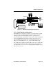
1.7.2.1 Virtual Switch Configuration Examples
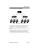
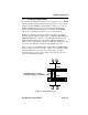
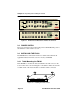
Figure 1-12 shows a 16-port FN100 configured as two virtual switches,
each attached to a separate non-Cabletron Systems device.
Figure 1-12 FN100 Virtual Switch Configuration Example #1
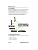
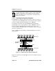
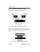
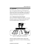
Figure 1-13 shows the FN100 configured as four virtual switches and
attached to a single non-Cabletron Systems device. Each virtual switch
provides a separate 100 Mbps connection to the non-Cabletron Systems
device.
Figure 1-13 FN100 Virtual Switch Configuration Example #2
FN100
100 Mbps
100 Mbps
Non-Cabletron Systems
Host Connection
Host Connection
Virtual
Switch 1
Virtual
Switch 2
(No Traffic)
Router
Non-Cabletron Systems
Router
FN100
100 Mbps
100 Mbps
SW1 SW2 SW3 SW4
Non-Cabletron Systems Device