
User guide

Chapter 2: Unpacking and Installing the FN100
Page 2-4 Fast Network 100 User Guide
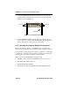
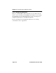
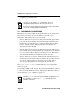
3. Secure the FN100 with the rack-mount fasteners by inserting and
securing a fastener through each of the four slots in the rack-mount
brackets, as shown in Figure 2-3.
Figure 2-3 Rack-mounting the FN100
4. Once the FN100 is installed, plug the AC power cord into the AC
power connector on the rear of the FN100 chassis. Plug the other end
of the power cord into a three-prong grounded outlet.
2.3.3 Checking the Power-up Diagnostics Sequence
Before connecting any devices to the FN100, power on the unit and
observe the power-up diagnostics sequence to check for proper operation.
To observe the power-up diagnostics sequence completely, you may want
to repeat it. To restart the power-up sequence, turn the power switch
OFF,
then
ON again, or press the reset button on the front panel.
When you power up the FN100, the following occurs:
1. All LEDs, except for the Port Link LEDs, turn on for one second.
2. The Power (Pwr) LED remains on.
3. The Ready LED starts flashing.
4. After several seconds, the Port Link and ACT LEDs flash briefly.
Fasteners
Rack
1X
2X
3X 4X 5X 6X
7X
8X
9X 10X 11X 12X 13X 14X 15X
16X
13 14 15 16
Link
23
1
4567
8
9101112
Status
Link
Status
Select
TX Act
Reset
Ready
FN100-16
NMS Port
Port
Status
Mode
100
Link
Status
Link
Status
1
9
TX
TX
RX
RX
RX Col Usr
Pwr
Fasteners