
User guide


Responses to Failures at Power Up
Fast Network 100 User Guide Page 5-3
5.1.4 Power-Up Diagnostics Results
After completion of the power-up diagnostic sequence, both the Power
(Pwr) and Ready LEDs located on the front panel of the FN100 should be
on.
5.2 RESPONSES TO FAILURES AT POWER UP
How the FN100 responds to failures detected during power-up depends
on the seriousness of the failure. For example, the FN100 will operate if a
non-critical component, such as the out-of-band management port, fails
diagnostics. However, in the event of a critical failure, such as a failure of
the management processor, the FN100 halts execution and does not boot
to operational mode.
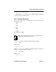
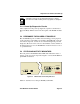
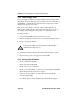
5.3 STATUS AND ACTIVITY INDICATORS
The front panel of the FN100 includes LEDs that indicate the status or
activity of various system components. Figure 5-1 shows the FN100 front
panel LEDs and buttons.
Figure 5-1 FN100 Status and Activity Indicators
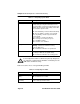
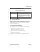
Table 5-1 describes how to interpret FN100 system LEDs.
NOTE
A backup version of the operational parameters is always
stored in non-volatile memory before any update is attempted.
1X
Link
Status
1
TX
RX
Ready
FN100-8
NMS Port
23
1
4567
8
Link
Status
Select
TX Act
Reset
Port
Status
Mode
100
RX Col Usr
Pwr