
User guide

Appendix A: Technical Specifications
Page A-6 Fast Network 100 User Guide
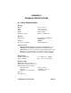
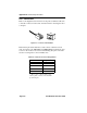
A.5.1 Connectors
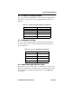
Refer to the diagram below and note how the pins are numbered. Be sure
to hold the connectors in the same orientation when connecting the wires
to the pins.
Figure A-1 Connector Pin Numbers
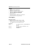
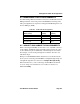
Each twisted-pair cable must have a male connector attached to both
ends. According to the 10BASE-T and 100BASE-TX specifications, pins
1 and 2 on the connector are used for transmitting data; pins 3 and 6 are
used for receiving data, as shown in Table A-6.
*. The “+” and “-” signs are used to repre-
sent the polarity of the two wires that make
up each wire pair.
Table A-6 RJ45 Crossover Pin Assignments
RJ45 Pin Assignment
*
1 Tx+
2 Tx-
3 Rx+
6 Rx-
1
8
8
1