HSIM-W84 Installation Guide HSIM-W84 T1-1 T1-2 T1-3 T1-4 ASYNC LNK LNK LNK LNK LNK STS STS STS STS STS CPU TELCO 9032718
Only qualified personnel should perform installation procedures. Notice Cabletron Systems reserves the right to make changes in specifications and other information contained in this document without prior notice. The reader should in all cases consult Cabletron Systems to determine whether any such changes have been made. The hardware, firmware, or software described in this manual is subject to change without notice.
Notice Industry Canada Notice This digital apparatus does not exceed the Class A limits for radio noise emissions from digital apparatus set out in the Radio Interference Regulations of the Canadian Department of Communications. Le présent appareil numérique n’émet pas de bruits radioélectriques dépassant les limites applicables aux appareils numériques de la class A prescrites dans le Règlement sur le brouillage radioélectrique édicté par le ministère des Communications du Canada.
Notice Exclusion of Warranty and Disclaimer of Liability 1. EXCLUSION OF WARRANTY. Except as may be specifically provided by Cabletron in writing, Cabletron makes no warranty, expressed or implied, concerning the Program (including its documentation and media).
Notice DECLARATION OF CONFORMITY Application of Council Directive(s): Manufacturer’s Name: Manufacturer’s Address: European Representative Name: European Representative Address: Conformance to Directive(s)/Product Standards: Equipment Type/Environment: 89/336/EEC 73/23/EEC 91/263/EEC Cabletron Systems, Inc. 35 Industrial Way PO Box 5005 Rochester, NH 03867 Mr. J.
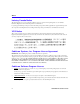
Contents CHAPTER 1 INTRODUCTION Structure of this Guide.....................................................................................1-1 Related Documents ..........................................................................................1-2 Document Conventions ...................................................................................1-2 Getting Help ......................................................................................................
Contents System Passwords ..................................................................................2-13 Simple Network Management Protocol (SNMP)....................................2-13 SNMP MIB Support ............................................................................2-13 Cabletron Enterprise MIBs ...............................................................2-14 SNMP Trap Support...........................................................................
1 Introduction Welcome to the Cabletron Systems HSIM-W84 Installation Guide. This guide provides basic configuration information, hardware specifications and troubleshooting tips for the HSIM-W84. This document also provides guidelines for routing and bridging over Wide Area Networks (WANs). Structure of this Guide This guide is organized as follows: Chapter 1, Introduction, details document conventions and provides information on getting help.
Chapter 1: Introduction Related Documents Use the Cabletron Systems QuickSTART Guide located in the QuickSET CD case to install the HSIM-W84. Use the READ ME FIRST! document included with the HSIM-W84 to set up your computer before beginning configuration. Use the Cabletron Systems CyberMONITOR User’s Guide with the CyberMONITOR product to monitor the performance of the WAN. Use this HSIM-W84 Installation Guide to connect your HSIM-W84 to a WAN using a Telnet connection.
Getting Help Getting Help If you need additional support related to this device, or if you have any questions, comments, or suggestions concerning this manual, contact the Cabletron Systems Global Call Center: Phone (603) 332-9400 Internet mail support@ctron.com FTP Login Password ctron.com (134.141.197.
Chapter 1: Introduction 1-4 HSIM-W84 Installation Guide
2 About the HSIM-W84 The HSIM-W84 (Figure 2-1) is a Wide Area Network (WAN) Remote Access High Speed Interface Module (HSIM). The HSIM-W84 supports OSI Layer 2 Inverse Multiplexing (IMUX) across groups of two, three, or four T1 ports, IEEE 802.1d transparent bridging, and IP/IPX Routing. In addition, the ASYNC port connector can be used as a local console connection.
Chapter 2: About the HSIM-W84 Additional Features FLASH EEPROMs — The HSIM-W84 uses FLASH Electrically Erasable Programmable Read-Only Memory (EEPROM) that allows the downloading of new and updated firmware in conjunction with Cabletron Systems QuickSET or any device using BootP or TFTP protocols. LANVIEW LEDs — Cabletron Systems LANVIEW Status Monitoring and Diagnostics System is a troubleshooting tool that helps in the diagnosing of power failures, collisions, cable faults, and link problems.
HSIM-W84 Firmware Support WAN Protocols This device supports the following WAN protocols over the WAN port: • Point-to-Point Compression Control Protocol (CCP) as defined by RFC 1962 • Point-to-Point Protocol (LCP) as defined by RFC 1661 • Point-to-Point Protocol (BNCP) as defined by RFC 1638 • Point-to-Point Protocol (IPCP) as defined by RFC 1473 • Point-to-Point Protocol (IPXCP) as defined by RFC 1552 • Frame Relay as defined by RFC 1490 • Frame Relay Data Compression Protocol (DCP) as defin
Chapter 2: About the HSIM-W84 Inverse Multiplexing NOTE Cabletron Systems products that support Inverse Multiplexing (IMUX), such as the HSIM-W84, HSIM-W6, CSX400, and CSX200, must exist on both ends of the WAN link for the IMUX function to work. Both bridging and routing functions are disabled when using the IMUX function.
HSIM-W84 Firmware Support HDLC Cabletron Systems has provided the High-level Data Link Control (HDLC) protocol which is used in conjunction with the Inverse Multiplexing (IMUX) feature to conserve a user’s WAN bandwidth between two Cabletron Systems products, over a point-to-point connection. Cabletron Systems products such as the HSIM-W6, HSIM-W84, CSX200, and CSX400 must be in use on both ends of the WAN link for these functions to work.
Chapter 2: About the HSIM-W84 The NAT method (that is supported only on interface T1-1) allows several DHCP clients on a sub network to connect to WAN clients by allowing the DHCP clients to share a single public IP address. When the HSIM-W84 uses NAT, the NAT method modifies the IP headers and addresses, and the selected fields in upper layer protocol headers.
HSIM-W84 Firmware Support Switched Virtual Circuits, or SVCs, are available on a call-by-call basis using the SVC signaling protocol (Q.933). The network must quickly establish the connection, and allocate bandwidth based on the user’s request. In a Frame Relay frame, user data packets are not changed in any way. A two byte header is appended to the frame. Contained in this header is a 10-bit number called the Data Link Connection Identifier (DLCI).
Chapter 2: About the HSIM-W84 IP-OSPF Hierarchy IP-OSPF operates within a hierarchy of entities: Autonomous System An Autonomous System (AS) is a set of routers and networks under a common administration. Routers inside an AS are called “interior gateways” and the protocol is called Interior Gateway Protocol (IGP). OSPF is an IGP. Every OSPF routing domain must have a backbone. An OSPF backbone distributes routing information between areas in an OSPF routing domain.
HSIM-W84 Firmware Support Designated Router Designated Routers (DR) are used by OSPF to reduce adjacencies. Other routers establish adjacencies and synchronize databases only with the designated router and backup designated router. These routers perform two key functions for the OSPF routing protocol: • The designated router creates a network links advertisement which lists the set of routers, including the designated router, attached to the network.
Chapter 2: About the HSIM-W84 In half-duplex operation, the authenticator device challenges the peer device by generating a CHAP challenge, and the challenge contains an MD5 algorithm with a random number that has your encrypted password and system name. The peer device then applies a one-way hash algorithm to the random number and returns this encrypted information along with the system name in the CHAP response.
HSIM-W84 Firmware Support Bridging and Routing Bridging — Bridging connects two or more separate networks together. The bridge examines a portion of each network frame called the header. This header contains control information for the frame.
Chapter 2: About the HSIM-W84 IEEE 802.1d Bridging — The HSIM-W84 supports the IEEE 802.1d standard for LAN to LAN bridging. This bridging algorithm learns the low-level MAC addresses of each LAN constituent and uses this information to decide whether to transmit the packet to another LAN via a WAN connection, or keep it local. Part of the bridging standard used, called Spanning Tree Protocol, supports multiple, redundant paths for LAN to LAN bridging, yet prevents data loops and duplication.
HSIM-W84 Firmware Support Common uses include preventing access to remote networks, controlling unauthorized access to the local network, and limiting unnecessary traffic. The HSIM-W84 supports the following Bridge Filters: • dot1d.Static Filters (IETF RFC 1493) • Ethernet Special Filtering Database (from the ctbridge-mib) System Passwords System passwords allow you to control access to the HSIM-W84 by establishing three passwords. Each password provides varying levels of access to the HSIM-W84.
Chapter 2: About the HSIM-W84 • DS1 and E1 MIB RFC 1406 (Digital Signal Level 1 [T1/E1 interface types]) • IETF Bridge MIB RFC 1493 • IP Forwarding MIB RFC 1354 • PPP LCP MIB RFC 1471 (Point-to-Point Protocol, Link Control Protocol) • PPP IPCP MIB RFC 1473 (IP Control Protocol) • PPP BNCP MIB RFC 1474 (Bridge Network Control Protocol) • IPXCP MIB RFC 1552 (PPP Internetworking Packet Exchange Control Protocol) • Frame Relay DTE MIB RFC 1315 • Security MIB RFC 1472 (CCP, PAP, and CHAP) • R
HSIM-W84 Firmware Support • Cabletron Enterprise Traps: • Port Segmented Trap Type Code #257(0x101)rrev4-mib • Port Operational Trap Type Code #258(0x102)rrev4-mib • Port Link Up Trap Type Code #259(0x103) rrev4-mib • Port Link Down Trap Type Code #260(0x106) rrev4-mib • Environmental Temperature Hot Trap Type Code #282(0x11A) brrev4-mib • Environmental Temperature Normal Trap Type Code #284(0x11C) rrev4-mib • IP Event Log Change Trap Type Code #1280(0x500) ctip-mib The following is a list of
Chapter 2: About the HSIM-W84 • • • • • • • • • • • • • IPX MTU size has been changed on interface # IPX Framing Type has been changed on interface # IPX has detected Link UP on interface # IPX has detected Link DOWN on interface # IPX Primary address has been changed on interface # IPX Access Control Lists have been enabled on interface # IPX Access Control Lists have been disabled on interface # IPX has detected Port UP (WAN devices only) IPX has detected Port DOWN (WAN devices only) IPX RIP has been en
3 Installation This chapter outlines the procedure for attaching the HSIM-W84 to the network. To install the HSIM-W84 you need the following items: • Antistatic wrist strap (provided with the HSIM-W84) • Phillips screwdriver Only qualified personnel should perform installation procedures. Unpacking the HSIM-W84 Unpack the HSIM-W84 as follows: 1. Remove the shipping material covering the HSIM-W84 in the shipping box. 2. Carefully remove the HSIM-W84 from the shipping box.
Chapter 3: Installation • In a shelf installation, the shelf must be able to support 13.6 kg (30 lb) of static weight for each device on the shelf. • Maintain a temperature of between 5°C (41°F) and 40°C (104°F) at the installation site with fluctuations of less than 10°C (50°F) per hour. • Maintain a two-inch clearance for each side and the back of the device for adequate ventilation. Installing an HSIM You can install an HSIM-W84 in any Cabletron Systems device that supports HSIM technology (e.g.
Installing an HSIM Standoff Screws Coverplate Faceplate Mounting Screws SmartSwitch Device 225704 Figure 3-1 Removing the HSIM Coverplate 7. Place the HSIM behind the module faceplate. See Figure 3-2. 8. Ensure that the standoffs on the interface module align with the standoff screw holes on the HSIM to prevent bending pins. Then insert the connector pins of the HSIM into the HSIM connector on the interface module. 9.
Chapter 3: Installation .
Installing an HSIM Installing an HSIM in a SmartSwitch Standalone Device To install an HSIM into a SmartSwitch standalone device that supports HSIM technology refer to Figure 3-1 and Figure 3-2, and perform the following steps: 1. Power down the standalone device and remove the power cord. 2. Disconnect all network cables from the standalone device. Note the ports to which these cables attach. Ensure that you remove the power cord and ONLY the screws required to remove the standalone device cover.
Chapter 3: Installation 12. Reattach the standalone device’s cover to the standalone device and reconnect the power cord. 13. Reconnect the standalone device to your network. CSX-COMP/ENCR Installation This section contains instructions on how to install the COMP/ENCR into the HSIM-W84. To help eliminate any potential problems during or after installation, read and understand the following steps: 1.
CSX-COMP/ENCR Installation Standoff Screws D-Type Connector Pins D-Type Connector CSX-COMP/ENCR Standoff Detail 2204N01 Figure 3-3 CSX-COMP/ENCR HSIM-W84 Installation Guide 3-7
Chapter 3: Installation 3-8 HSIM-W84 Installation Guide
4 Troubleshooting Use this chapter in conjunction with the LANVIEW status monitoring and diagnostic LEDs on the HSIM-W84 to diagnose power failures, cable faults and link problems. Figure 4-1 shows the front panel LEDs. Table 4-1 through Table 4-5 describe the LED states of the HSIM-W84. If you are having difficulty installing and configuring the HSIM-W84, perform the following steps: • Review the HSIM-W84 QuickSTART Guide to insure proper installation.
Chapter 4: Troubleshooting Table 4-2 HSIM-W84 ASYNC LED States (Console Connection Only) LED Color Status (STS) Link (LNK) State AMBER Console connection; Data Carrier Detect (DCD); No Data Set Ready (DSR) AMBER (blinking) Test mode GREEN Modem with connection; DCD; DSR GREEN (blinking) Modem, no connection; DSR; No DCD RED Modem connection; Request To Send (RTS); No Clear To Send (CTS) AMBER (blinking) Traffic; Modem or console connection GREEN Modem connection; RTS; CTS asserted Table 4
Troubleshooting Table 4-4 HSIM-W84 WAN Link (LNK) LED States LED Link (LNK) Color State OFF WAN interface not configured RED No Link/Connection (Fault) on the WAN interface AMBER Transmit (TX) and/or receive (RX) traffic GREEN Link and port is active GREEN (blinking) Link and port is in standby Table 4-5 HSIM-W84 WAN Status (STS) LED States for T1 Ports LED Color State OFF Normal or disabled RED Red Alarm AMBER Yellow alarm AMBER (blinking) Port in test mode Status (STS) HSIM-W84 I
Chapter 4: Troubleshooting Troubleshooting HSIM-W84 Hardware The following sections describe the LED states for the hardware, ASYNC console connection, and WAN connection, and show how to troubleshoot the HSIM-W84 based on these LED states. SmartSwitch Standalone or Module Power (PWR) LED is OFF — Check that the power connection is firmly attached to the back panel of the SmartSwitch Standalone or Module, and the other end to an active power source.
Troubleshooting HSIM-W84 Hardware Troubleshooting the WAN Link (LNK) LED is OFF — The WAN interface is not configured for operation. Use QuickSET or Local Management to make sure that the WAN interface is configured correctly. Link (LNK) LED is RED — The WAN interface is configured, but there is no signal indicating that a valid connection is present on the WAN interface. • Check that the HSIM-W84 and the device at the other end of the segment are powered up.
Chapter 4: Troubleshooting Status (STS) LED is AMBER — The device is in Yellow alarm mode. A Yellow alarm indicates that the HSIM-W84 is receiving proper framing from the Telco, but the Telco is not receiving proper framing. • Check for faulty or incorrect cabling between Telco and HSIM-W84. • Request that the Telco verify the configuration and operation of the circuit. Status (STS) LED is AMBER (blinking) — Device is in test mode. • The HSIM-W84 is running its Power-up Diagnostic Tests.
Investigating Software Configuration Problems User Cannot Communicate with Remote Network Station If Bridging, • Check that the Bridging Default Destination is set. • Check that bridging to/from the remote router is set on. • Be sure to reboot if you have made any bridging destination or control changes. If TCP/IP Routing, • Check that TCP/IP Routing is set on and is enabled at the remote end.
Chapter 4: Troubleshooting The information provided in a FULL STATUS RESPONSE, or ASYNCHRONOUS STATUS MESSAGE basically has two parts, the FR Switch provides a DLCI number, and whether that DLCI is in the Active or Inactive state. Active State — means that both ends of the connection (this DTE and the DTE at the other end of the WAN cloud) are speaking correctly to the FR DCE Switches in the WAN cloud.
A NOTE T1 Cable Specifications For T1 cables, observe the following part numbering conventions when ordering a standard 20-foot cable or a specified length of cable. The number 20 followed by the part number denotes the standard 20-foot cable. The letter “L” denotes the specified length required in feet or meters. For example: 9372095-3 denotes a 3 foot cable; 9372095-3M denotes a 3 meter cable.
Appendix A: T1 Cable Specifications Table A-3 provides RJ48 DTE pin assignments. Table A-3 DTE Pin Assignments Pin Signal 1 Receive Ring 2 Receive Tip 3 Not Used 4 Transmit Ring 5 Transmit Tip 6 Not Used 7 Shield Ground 8 Shield Ground Table A-4 provides RJ48 network pin assignments.
B Specifications and Standards Compliance This chapter contains hardware specifications, and safety and compliance standards for the HSIM-W84.
Appendix B: Specifications and Standards Compliance B-2 HSIM-W84 Installation Guide
C FCC Part 68 - User’s Information For HSIM-W84 The following instructions are to ensure compliance with the Federal Communications Commission (FCC) Rules, Part 68: 1. All connections to the HSIM-W84 must be made using standard plugs and jacks. 2. Before connecting your unit, you must inform the local telephone company of the following information: Table C-1 Port ID HSIM-W84 REN/SOC 6.0N HSIM-W84 FIC 04DU9-BN 04DU9-DN 04DU9-1KN 04DU9-1SN 04DU9-1ZN USOC RJ48C RJ48X 3.
Appendix C: FCC Part 68 - User’s Information For HSIM-W84 AFFIDAVIT FOR THE CONNECTION OF CUSTOMER EQUIPMENT TO 1.544 MBPS AND/OR SUBRATE DIGITAL SERVICES For the work to be performed in the certified territory of Telco’s name: State of: Country of: I, , of (Name of Authorized Representative) (Customer Name) , (Customer’s Address) (Telephone Number) being duly sworn, state: I have responsibility for the operation and maintenance of the terminal equipment to be connected 1.
FCC Part 68 - User’s Information For HSIM-W84 I attest that the operator(s) maintainer(s) of the digital CPE responsible for the establishment, maintenance and adjustment of the encoded analog content and billing information has (have) been trained to perform these functions by successfully completing one of the following: Check appropriate one(s). a. A training course provided by the manufacturer/grantee of the equipment used to encode analog signals; or b.
Appendix C: FCC Part 68 - User’s Information For HSIM-W84 C-4 HSIM-W84 Installation Guide
D Glossary 10BASE-T — IEEE 802.3 standard for the use of Ethernet LAN technology over Unshielded Twisted Pair wiring, running at 10 Mbps. ARP — Address Resolution Protocol. An Internet protocol used to bind an IP address to Ethernet/ 802.3 addresses. ASCII — American Standard Code for Information Interchange. It is an 8-bit code for character representation. AUI — Attachment Unit Interface. An IEEE 802.3 transceiver cable connecting the network device (such as a router) to the MAU (media access unit).
Appendix D: Glossary DTMF — Dual Tone Multi-Frequency. TOUCHTONE as opposed to Dial Pulse (DP). DTR — Data Terminal Ready. RS-232 signal used for indicating to the DCE the readiness to transmit and receive data. EtherTalk — AppleTalk protocols running on Ethernet. Filter — Feature to control the flow of data based on protocol or bridge information. Filters can be specific to allow data through or prevent transmission.
Glossary MAC Layer/Address — Media Access Control layer/address defined by the IEEE 802.3 specification which defines media access including framing and error detection. Part of the OSI reference model Data Link layer. Metric — An algorithm used by routers to determine the best path for transmitting packets to a remote destination based on considerations such as time, delay, cost, etc. Modem — Modulator/Demodulator.
Appendix D: Glossary RFC — Request for Comment. Documentation describing Internet communications specifications (e.g., Telnet, TFTP). Often these RFCs are used to achieve multi-vendor interoperability during implementation. RJ11 — Standard 4-wire connectors for telephone lines. RJ45 — Standard 8-wire connectors for computer networks. RIP (Routing Information Protocol) — Protocols used in IP and IPX for broadcasting open path information between routers to keep routing tables current.
Glossary Subnet Address — An extension of the Internet 32-bit addressing scheme that allows the separation of physical or logical networks within the single network number assigned to an organization. TCP/IP entities outside this organization have no knowledge of the internal “subnetting.” Subnet Mask — A 32-bit internet protocol address mask used to identify a particular subnetwork. TCP/IP — Transmission Control Protocol/Internet Protocol. Refers to a set of internetworking protocols developed by the U.
Appendix D: Glossary D-6 HSIM-W84 Installation Guide
Index B R Bridge filtering 2-12 Bridging 2-11 Bridging and routing 2-11 Remote Network Management 2-2 Routing 2-11 F S Getting Help 1-3 SNMP 2-13 SNMP Community Names read-only 2-13 read-write 2-13 super-user 2-13 Software and firmware upgrades 2-16 H T Firmware Data Compression 2-4 Flash EEPROMs 2-2 G IEEE 802.
Index Index-2 HSIM-W84 Installation Guide