a QUICK REFERENCE GUIDE FOR NETWORK TROUBLESHOOTING
NOTICE Cabletron Systems reserves the right to make changes in specifications and other information contained in this document without prior notice. The reader should in all cases consult Cabletron Systems to determine whether any such changes have been made. The hardware, firmware, or software described in this manual is subject to change without notice.
Notice ii Troubleshooting Guide
CONTENTS CHAPTER 1 INTRODUCTION 1.1 How to Use This Guide......................................................................................................................... 1-1 1.2 Structure of This Guide......................................................................................................................... 1-2 1.3 Document Conventions ........................................................................................................................
Contents CHAPTER 6 FDDI PROBLEMS 6.1 Workstation on Ethernet Network Cannot Communicate with Server on FDDI Ring........................... 6-2 6.2 Workstation and Server on the Same FDDI Ring Cannot Link ............................................................ 6-5 6.3 Replaced a Concentrator Module, but the Ring Does Not Recognize It.............................................. 6-6 6.4 Installed a New Dual Attached Device, but the Ring Does Not Recognize It ......................................
CHAPTER 1 INTRODUCTION This guide is intended for use by network managers and technicians as an aid in identifying possible causes to various types of network problems. Details on how to perform tests, use network management applications, and LANVIEW LEDs are not covered except in a few isolated cases where the information appears in examples or in the form of a note called, TIP. LANVIEW LEDs used on Cabletron Systems modules or standalone devices may vary.
Chapter 1: Introduction 1. Refer to Section 2.1, Problem Identification and Notification, for guidelines to gather relevant information about the network to determine how, or if part or all of the network is affected. 2. Refer to Section 2.2, Problem Verification and Information Gathering, for guidelines about how to verify that a problem actually exists and gather relevant information about the problem. 3. Refer to Section 2.
1.3 Document Conventions The following conventions are used throughout this document: • NOTE - Calls the reader’s attention to any item of information that may be of special importance. • TIP - Conveys helpful hints concerning procedures or actions. • Code examples, commands, and displayed messages are shown in courier type face. • Combination key strokes are shown hyphenated such as CTRL-L, which indicates that you press both the CTRL key and the L key.
Chapter 1: Introduction 1-4 Troubleshooting Guide
CHAPTER 2 TROUBLESHOOTING GUIDELINES This chapter provides guidelines on what to do when someone suspects that there is a problem with the network.
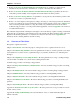
Chapter 2: Troubleshooting Guidelines START REFER TO SECTION 2.1 IDENTIFY PROBLEM & NOTIFY USERS OF THE PROBLEM REFER TO SECTION 2.2 YES WAS THE PROBLEM IDENTIFIED TO A CATEGORY? VERIFY THAT THERE IS A PROBLEM TAKE INTO ACCOUNT NEW INFORMATION AND CHANGES IN THE NETWORK NO REFER TO SECTION 2.
A REFER TO SECTION 2.6 ISOLATE THE PROBLEM USE ALL TOOLS AVAILABLE TO GATHER DATA CAN A SUSPECT UNIT BE IDENTIFIED? NO TROUBLESHOOT USING CUT BY HALF (DIVIDE/CONQUER" METHOD TO FIND THE SUSPECT UNIT YES CAN A SUSPECT UNIT BE IDENTIFIED? NO TROUBLESHOOT USING KNOWN GOOD DEVICE METHOD TO FIND THE SUSPECT UNIT YES HAS THE PROBLEM BEEN ISOLATED TO A CATEGORY? NO C To Sheet 1 YES B To Sheet 1 1930-03 Figure 2-2.
Chapter 2: Troubleshooting Guidelines 2.1 Problem Identification and Notification How did someone notice that there is a problem, and how far-reaching is it? Gather all the information relevant to the perceived problem.
4. Check to see if the network has been changed recently in any way by adding, removing, upgrading or reconfiguring any of its elements? Was the problem narrowed down to one of the categories in Chapters 3 through 9? If YES, refer to the appropriate chapter for instructions on how to remedy the most common problems in that category. If NO, go to step 5. 5. Look at the release notes to see if there are any incompatibilities or known issues.
Chapter 2: Troubleshooting Guidelines 5. If the problem has not been remedied, proceed as follows: a. Repeat steps in Sections 2.2, 2.3, and 2.4 until a solution is found within a reasonable period of time. The possibilities should narrow down until either a solution is found or the problem is found to be unsolvable by the persons applying this method. b. Depending on the severity or urgency of the problem, call in other experts such as Cabletron Systems Technical Support. 2.
2. What tools do you have for troubleshooting? Have you used the tools in this situation, and what were the results? For example: a. Using a Lanalyzer or sniffer (refer to its manual for operating instructions) 1.) Did you get a trace of the failure? 2.) Do you have a trace of normal network activity? 3.) What is the traffic rate, normal and at the time(s) of the failure(s)? b.
Chapter 2: Troubleshooting Guidelines 4.
CHAPTER 3 BOOTING/IMAGE CODE LOADING PROBLEMS This chapter provides guidelines with some procedures for booting or loading an image code from a PC, or workstation, to a device such as a management module in a network environment. In this category of problems, there is only one problem and that is you cannot boot or download an image code to a device such as a management module.
Chapter 3: Booting/Image Code Loading Problems 3.1 TFTP and BootP Download Guidelines for Personal Computers (PC) Section 3.1.1 through Section 3.1.4 provide guidelines on how to use a PC running SPECTRUM Element Manager for Windows, or Remote LANVIEW for Windows (Versions 2.1 or 2.0x) application to TFTP download to a device using Netmanage or Microsoft’s TCPIP (MSTCPIP) application.
Figure 3-1. Netmanage NEWT Table and ARP Table Screens 3. Find the IP address to Hardware (MAC) address correlation of the device that you want to TFTP download and enter it in the Frequent Destinations table. For example: Refer to the ARP Table shown in Figure 3-1 and assume that the IP address for the device is 128.20.1.100. The associated hardware address is 00:00:1D:13:12:CB. 4. To enter this information (IP addresses and Hardware addresses) into the Frequent Destinations table, proceed as follows: a.
Chapter 3: Booting/Image Code Loading Problems Figure 3-2. CUSTOM and Frequent Destination Screens 3.1.1.2 TFTP for MSTCPIP In this situation you must also set up the ARP Table. To do this, proceed as follows: 1. Go to the MS DOS prompt and type arp -a at the command line. A list of the dynamic entries is displayed (Figure 3-3). 2. Find the IP (logical address) to MAC address (physical address) correlation of the device that you want to TFTP download. 3.
Figure 3-3.
Chapter 3: Booting/Image Code Loading Problems 3.1.2 TFTP Downloading Using a PC with SPEL To TFTP download using SPEL, proceed as follows: 1. Click on the TFTP tool bar icon or click on utilities, then the tftp/bootp pulldown menu. You must have an icon selected or this will be grayed out. The Start Download screen is displayed (Figure 3-4). 2. Click on Browse button and find the file for download. The filename and path should not exceed more than 25 characters. The example c:\emme.
3.1.3 TFTP Downloading Using a PC with Remote LANVIEW, Version 2.10 To TFTP download using Remote LANVIEW 2.10, proceed as follows: 1. While highlighting the device icon to which you are going to download, pull down the Control menu and highlight TFTP Download. The TFTP Download screen displays (Figure 3-5). 2. Click on the Browse button near the bottom of the TFTP Download screen and find the file with the .hex extension that is to be used for download.
Chapter 3: Booting/Image Code Loading Problems 3.1.4 TFTP Downloading Using a PC with Remote LANVIEW, Version 2.0x Remote LANVIEW 2.0x uses a proprietary IP stack. If you have a green icon (such as the EMME icon shown in Figure 3-6) for the device to which you want to TFTP download, no ARP entry is needed. Just pull down the Control menu and then the TFTP Download menu. Figure 3-6. Control Pulldown Menu and TFTP Download Window 3.
Therefore, if you are using a multiple interface device like the EMME or EMM-E6, make sure you use the correct MAC address. An EMME has four MAC addresses. The white label on the front of the EMME shows the MAC address for the first channel (A). You need to increment the address to the channel that your Network Manager Station comes in on.
Chapter 3: Booting/Image Code Loading Problems 3. Click on the BootP Server tab. The BootP Server screen (Figure 3-8) is displayed. Figure 3-8. BootP Server Screen 4. Enter the correct MAC address in the MAC Address field while making sure to use hyphens. 5. Enter the IP address in the IP Address field using periods (Dot Decimal Notation). 6. Enter the filename by using the Browse button. The filename and path should not exceed more than 25 characters. For example, c:\emme.hex uses 11 characters.
3.2.2 BootP Downloading Using a PC with Remote LANVIEW 2.10 To use Remote LANVIEW 2.10 for BootP, proceed as follows: 1. Make sure that you follow the ARP cache or Frequent Destination instructions provided in Section 3.1.1, step 3, before configuring Remote Lanview 2.10. 2. Click the pulldown menu under Control, then TFTP Download. This brings up the icon shown in Figure 3-9. Figure 3-9. BootP Icon 3. Double click on the BootP icon, then pull down the configure menu and select Configure BootP Server.
Chapter 3: Booting/Image Code Loading Problems Unlike SPECTRUM Element Manager, there is no easy way to tell if BootP has begun. Although they are not as easy, there are other ways to tell as follows: • • • Use the Local Management of the device to locally view the download. Check your hard drive LED to see if it is continuously reading your hard drive. Use the UDP Statistics screen of your network management application. This will show numerous UDP packets being sent and received. 3.2.
3.3 TFTP Downloading Guidelines for UNIX Stations Section 3.3.1 through Section 3.3.4 provide general guidelines to set up a UNIX workstation as a TFTP or BootP server. The examples given are general in nature and may not be specific to your UNIX Operating System. For information specific to your UNIX system, refer to the appropriate supporting documentation. NOTE: Before upgrading firmware, read the firmware release notes to make sure the boot revisions, etc., are compatible.
Chapter 3: Booting/Image Code Loading Problems Do this: 30101.hex TIP: To avoid TFTP download failures, always use the /tftpboot directory structure and secure mode (look for the “-s /tftpboot” option in the inetd.conf). When using this technique, you ONLY HAVE TO ENTER the image filename and NOT THE FULL PATH NAME. This is a very important step, as some UNIX stations use tftpboot as a default whether or not the secure mode is used. If you specify a full path, the tftp download will fail.
3. Now you are ready to start the TFTP download process. Use your network management application to enter the appropriate information and start the TFTP process. 3.3.3 Setting Up UNIX Station as BootP Server Going Across a Router to the Device To set up a UNIX station as a BootP server going across a router to a device, proceed as follows: 1. Refer to the instructions in the supporting document for your UNIX station to correctly set up your BootP environment. 2. Perform steps 1 through 3 of Section 3.3.
Chapter 3: Booting/Image Code Loading Problems Download Requirements: The file transfer from a UNIX station to the device is done by using TFTP (Trivial File Transfer Protocol), which is connectionless. This can be initiated on a device from a Network Management System. If that device will not accept a TFTP download, then BootP (Bootstrap Protocol) is used.
Failed RARP Requests (Got a MAC, need the IP): The device (for example, an EMME) sends out a RARP request with its MAC address and uses the TID portion of the packet to target the IP address of itself, 134.141.55.25. The RARP request will fail if the EMME RARPs with a TID IP address of 0.0.0.0 rather than 134.141.55.25. Then the device will just reboot. If this is the failure, you can fix this in one of two ways: either re-assign the IP address at the device, via LM, or clear NVRAM on the device.
Chapter 3: Booting/Image Code Loading Problems 3-18 Troubleshooting Guide
CHAPTER 4 DESKTOP NETWORK INTERFACE (DNI) PROBLEMS This chapter provides a troubleshooting guide that identifies some of the more common problems related to DNI cards in a PC or workstation. Refer to the following list and proceed to the appropriate section shown in parentheses for the possible causes and remedy. NOTE: DNI cards are also known as Network Interface Cards (NICs). 1. After Installing an E22xx Ethernet Card in a Novell Server, Users Cannot Connect — (Section 4.1) 2.
Chapter 4: Desktop Network Interface (DNI) Problems 4.1 After Installing an E22xx Ethernet Card in a Novell Server, Users Cannot Connect Check the Startup.ncf file on the Novell Server. Is the “Set Maximum Physical Receive Packet Size” set to at least 1518? Y N Set the maximum packet size to 1518. The frame type (Ethernet-802.2, -802.3, -II, or SNAP) being used on the client and server Personal Computers (PCs) may not be the same. Are the frame types different? Y N Call Cabletron Technical Support.
4.4 T2015 Token Ring Card Passes Diagnostics, but When Trying to Load the Driver, the Card Will Not Insert Onto the Ring Check that the I/O settings configured in the software match the I/O switch settings on the T2015 faceplate. Are the settings different? Y N Check if the correct port is being assigned through the software: Primary = STP and Secondary = UTP. Are the ports being correctly assigned? Y N Assign the ports correctly: Primary = STP and Secondary = UTP.
Chapter 4: Desktop Network Interface (DNI) Problems 4.6 Client Driver Loads, but Cannot Find Any Novell Servers Check the Link, Transmit, and Receive LEDs on the DNI card. Is the Link LED lit and are the Transmit and Receive LEDs blinking? Y N Ensure that the correct media is selected, verify that the cable is okay, or try a different port on the hub. Did this solve the problem? Y N Call Cabletron Technical Support. Congratulations, the problem is solved.
4.7 After Connecting an Unshielded Twisted Pair (UTP) Cable, There Is No Link on the F7019 Card The cable may have the wrong pinout. Check the cable for the following pinout. Pin 1 to Pin 7 Pin 2 to Pin 8 Pin 7 to Pin 1 Pin 8 to Pin 2 Does the cable have the correct pinout? Y N Replace the cable with one that does have the correct pinout. Is there a Link with the F7019 card? Y N Call Cabletron Technical Support. Congratulations, the problem is solved. Call Cabletron Technical Support. 4.
Chapter 4: Desktop Network Interface (DNI) Problems 4.9 When Loading the Driver for E22xx, There Is an Error Message “invalid i/o address” When the driver for the E22xx Card was loaded in the PC, the error message “invalid i/o address” was displayed. Running E22_TEST.EXE caused the message “no E22xx adapter found” to display. Is the PC PnP compliant? Y N Run QuickSet 2.04 or above and set the “Plug and Play System” to NO.
CHAPTER 5 ROUTING PROBLEMS This chapter provides a troubleshooting guide that identifies some of the more common routing problems in a network environment. Refer to the following list and proceed to the appropriate section shown in parentheses for the possible causes and remedy. 1. Cannot Set a Router to the Enable Mode — (Section 5.1) 2. The Router Does Not Boot Normally — (Section 5.2) 3.
Chapter 5: Routing Problems 5.1 Cannot Set a Router to the Enable Mode Ensure that the password was entered correctly. The entry is case sensitive. If there are upper and lower case characters in the password, ensure that they are entered correctly. Was the password entered correctly? Y N Enter the password correctly. Are you still having a problem setting the router into the enable mode? Y N Congratulations, the problem is solved. Verify that the password that you are using is the correct password.
5.2 The Router Does Not Boot Normally With a terminal or PC connected to the router COM or CONSOLE port, access the Local Management application and note the prompt displayed, if any. Did the “Router(boot)>” prompt display? Y N Did the “System Configuration Dialog” display with the following message? Configuration interface IP parameters for netbooting: Y N Did the System Configuration Dialog display? Y N Call Cabletron Technical Support. Enter the information requested. Then press Return.
Chapter 5: Routing Problems A B C D Type in: reload Press Return. Type in: y Does the router boot normally? Y N Call Cabletron Technical Support. Congratulations, the problem is solved. There may be a corrupt FLASH image. Download a new image to your router. Refer to your router documentation for instructions. Did the prompt “Router(boot)>” display? Y N Call Cabletron Technical Support. Congratulations, the problem is solved. For Cisco Model IGS (with firmware revisions 9.
A B Y N Call Cabletron Technical Support. Wait until the router stops trying to load its configuration off the network. Press Return. The prompt Router > displays. At the prompt, type in: en and enter the enable password. Type in: config t Press Return. Type in: no service config Press Return. Press CTRL-Z Press Return. Type in: wr Press Return. Type in: reload Press Return. Type in: y Does the router boot normally? Y N Call Cabletron Technical Support. Congratulations, the problem is solved.
Chapter 5: Routing Problems 5.3 Device Cannot Establish IP Communication with Another Device Across a Router, but Can Establish IP Communication Locally Cannot establish IP communication from a PC across a router to a device in another network. See Figure 5-1. Network Network PC E1 Interface Router EØ Interface Server Unreachable Device 1930-01 Figure 5-1. Example of Network Try pinging across the router to other devices on the same network of the unreachable device.
A B Was the router able to ping the unreachable device? Y N Type in: clear arp Press Return. Type in: ping IP_ address where IP_address is the IP address of the unreachable device. Press Return. Was the router able to ping the unreachable device? Y N Type in: show config Check the display to see if the IP address and subnet mask are set correctly for the E1 interface. Both the E1 interface and the unreachable device must be on the same network/subnet.
Chapter 5: Routing Problems 5.4 Cannot Communicate with Another IP Network, Network Not Listed or Listed as Unreachable in Router Routing Table Cannot communicate with another IP network. Entered the command, show ip route to display the routing table, but the IP network is either not listed or listed as being unreachable. Depending on the complexity of the whole network, there may be one or more routers between your router and the network that is unreachable.
A Are the routers running the same routing protocol? Y N Configure both routers so they are running the same routing protocol such as RIP, IGRP, or OSPF. NOTE: If you cannot configure both routers to run the same protocol, call Cabletron Technical Support. With both routers running the same protocol, is the unreachable network still unreachable? Y N Congratulations, the problem is solved.
Chapter 5: Routing Problems 5.5 Configured an EMM-E6 or NBR Series Bridge for Routing, but It Doesn’t Work The EMM-E6 or NBR device needs an 8Mb memory upgrade for it to function as a router. Has a memory upgrade been installed to support routing? Y N An 8Mb memory upgrade is needed. Contact Cabletron Systems Sales for information about purchasing the correct memory upgrade needed for your EMM-E6 or NBR device. Make sure the memory upgrade was installed correctly.
A B Clear the NVRAM and reconfigure the EMM-E6 or NBR router. Refer to the following note. NOTE: When clearing NVRAM, all user entered parameters are erased and replaced with the default parameters. After reconfiguring the EMM-E6 or NBR, is it routing? Y N Call Cabletron Technical Support. Congratulations, the problem is solved.
Chapter 5: Routing Problems 5-12 Troubleshooting Guide
CHAPTER 6 FDDI PROBLEMS This chapter provides a troubleshooting guide that identifies some of the more common problems in the FDDI network environment. Refer to the following list and proceed to the appropriate section shown in parentheses for the possible causes and remedy. 1. Workstation on Ethernet Network Cannot Communicate with Server on FDDI Ring — (Section 6.1) 2. Workstation and Server on the Same FDDI Ring Cannot Link — (Section 6.2) 3.
Chapter 6: FDDI Problems 6.1 Workstation on Ethernet Network Cannot Communicate with Server on FDDI Ring A workstation (or PC) on the Ethernet network cannot communicate with a server on an FDDI Ring. The Ethernet network is bridged to the FDDI Ring using a Cabletron Systems FDMMIM bridge module. Check the FDMMIM module to ensure that it is not in the standby mode. Is the FDMMIM in standby mode? Y N Check the frame type to make sure that the Ethernet workstation is not set to the 802.3 frame type.
A B C Can the users connect with the server? Y N Call Cabletron Technical Support. Congratulations, the problem is solved. Call Cabletron Technical Support. Using the Chassis Status View screen in Local Management or using a network management application such as SPEL or SPECTRUM, enable the FDMMIM (take it out of standby mode). Can the workstation communicate with the server? Y N Check the frame type to make sure the workstation is not set to the 802.3 frame type.
Chapter 6: FDDI Problems A B C Can the workstation communicate with the server? Y N The DNI card in the workstation may not be configured correctly. Check the Startup.ncf file on the server. Is the “Set Maximum Physical Receive Packet Size” set to at least 1518? Y N Set the maximum packet size to 1518. The frame type (Ethernet-802.2, -802.3, -II, or SNAP) that is being used on the workstation and server may not be the same. Are the frame types different? Y N Call Cabletron Technical Support.
6.2 Workstation and Server on the Same FDDI Ring Cannot Link Both the workstation and server are connected to a ring concentrator. Can any other workstation on the ring communicate with the server? Y N Check the DNI card configuration of the server. Novell only supports FDDI_802.2 and FDDI_SNAP and does not support Ethernet 802.3. Are the Ethernet clients using Ethernet 802.3? Y N Call Cabletron Technical Support.
Chapter 6: FDDI Problems 6.3 Replaced a Concentrator Module, but the Ring Does Not Recognize It A concentrator module such as a 9F12x-xx or FDCMIM-x was replaced, but now the ring does not recognize that concentrator. Is the revision level of the concentrator firmware at the same revision level as the other concentrators in the hub? Y N Call Cabletron Technical Support. Try to install the concentrator into a different slot in the hub.
Are the LED indications different? Y N Ensure that all cables have been installed according to the X3T9.5 ANSI standards. Correct as necessary to bring the cables within standards. Does the ring recognize the new dual attached device? Y N Call Cabletron Technical Support. Congratulations, the problem is solved. Congratulations, the problem is solved. 6.5 Ring Is Running Slower Than Expected Is the ring within the X3T9.5 ANSI standard? Y N Correct the ring as necessary to bring it in within the X3T9.
Chapter 6: FDDI Problems 6-8 Troubleshooting Guide
CHAPTER 7 ETHERNET PROBLEMS This chapter provides a troubleshooting guide that identifies some of the more common problems in an Ethernet network environment. Refer to the following list and proceed to the appropriate section shown in parentheses for the possible causes and remedy. 1. Cannot Access Local Management — (Section 7.1) 2. Connected Two Hubs Together, but Cannot Pass Traffic Between Them — (Section 7.2) 3. Observing Excessive Collisions on a Network Repeated Segment — (Section 7.3) 4.
Chapter 7: Ethernet Problems 7.1 Cannot Access Local Management Cannot access Local Management (LM) through the terminal or PC connected to an intelligent device. The PC has a Windows terminal emulation application. Can you access the password screen? Y N Ensure that the correct cable is used to connect the terminal to the correct port on the intelligent device. Refer to the device documentation for cabling information and COM port usage.
7.2 Connected Two Hubs Together, but Cannot Pass Traffic Between Them Two hubs (standalone or modular) are connected together, but they will not pass traffic. Check the LINK LEDs of the device ports that are used to connect the two hubs. Are their LINK LEDs lit? Y N Check the cable used to connect the two hubs to ensure that it is the correct cable and it is not defective. Refer to the hub or device documentation for details about cable connections between two hubs.
Chapter 7: Ethernet Problems 7.3 Observing Excessive Collisions on a Network Repeated Segment Collision (CLN) LED or network management application, such as SPEL or SPECTRUM, indicates that there are more collisions than expected on a repeated segment of the network. Are there any transceivers attached to the segment with the SQE feature enabled? Y N Is the segment connected to a standalone hub such as an SEHI? Y N It is assumed that the segment is connected to a modular hub.
A B C The problem may be with the cabling or the attached user device. Check the cable and device to make sure the cabling used is the correct one and that it is not damaged. Also check the device for any indications of a problem. Correct as necessary. Then reconnect the user device to the standalone hub. Did the number of collisions remain reduced? Y N Call Cabletron Technical Support. Congratulations, the problem is solved.
Chapter 7: Ethernet Problems 7.4 User Configurable Parameters for a Device Are Lost When That Device Is Powered Down Does the device have a battery backup feature for NVRAM? Y N Check the NVRAM reset switch for proper setting. Refer to the device documentation for the proper setting. Power up the device. Reenter the user configurable parameters. Power down the device. Then power up the device to see if the new parameters were retained.
7.5 ESX Will Not Pass Traffic Through MMAC-MxFNB, Ethernet Channel A The ESX (ESXMIM or ESXMIM-F2) will not pass traffic through Ethernet Channel A in an MMAC-MxFNB. Is the Channel A LANVIEW LED lit on the ESX? Y N Access Local Management in the ESX and change the port 1 configuration from RJ45 to A Channel. Then check to see if the Channel A LANVIEW LED is lit. Did the Channel A LANVIEW LED light? Y N Call Cabletron Technical Support.
Chapter 7: Ethernet Problems 7-8 Troubleshooting Guide
CHAPTER 8 TERMINAL SERVER PROBLEMS This chapter provides a troubleshooting guide that identifies some of the more common problems related to terminal servers in a network environment. Refer to the following list and proceed to the appropriate section shown in parentheses for the possible causes and remedy. NOTES: In this chapter, the term “CSMIM2” also refers to the CSMIM, MODMIM, MicroCS, and CSMIM-T1 devices unless it is specified differently.
Chapter 8: Terminal Server Problems 8.1 No monitor: Prompt No monitor: prompt displayed at the CSMIM2. Is your terminal connected to Port One of the CSMIM2? Y N Connect to Port One using a straight-through 8-wire cable and Cabletron adapter (Part Number 9372074) to set up an asynchronous terminal. Did monitor: prompt appear? Y N Did you get an error message? Y N Call Cabletron Technical Support. Note the error message and call Cabletron Technical Support. Congratulations, the problem is solved.
8.2 Was Running, Had Power Outage, Now Won’t Boot, Was Booting from UNIX Host. A CSMIM2 was running before a power outage occurred, and now it will not boot from the UNIX host. Check that the boot host is running. Is the boot host running? Y N Try to start boot host. Did the host boot without errors? Y N You may have to correct disc errors and/or recover files from the backup tapes. Correct as needed and try to restart the boot host. Did the host boot? Y N Contact the host vendor for technical support.
Chapter 8: Terminal Server Problems A Are all the addresses correct? Y N Correct the addresses as necessary. Enter the image -d command. Three or four lines of data will display. Check the top line to see if the image name and the revision level of the software running on the UNIX host are appropriate for the device as shown in Table 8-1. Table 8-1. Devices/UNIX Software/Image Name Device Software CSMIM CSMIM2 and MODMIM MicroCS MicroCS MODMIM, CSMIM-T1, CSMIM, and CSMIM2 Software Rev. 7.X through 9.x 8.
8.3 Was Running, Had Power Outage, Now Won’t Boot, Was Booting from FLASH A CSMIM2 was running before a power outage occurred, and now it will not boot. The CSMIM2 was booting from FLASH. Place the CSMIM2 in the Setup Mode. To do this reseat the CSMIM2. Slide the module out of the hub and then reinsert. Lock the card in place using the thumb screws. Press the RESET button within 30 seconds of reseating the card.
Chapter 8: Terminal Server Problems 8.4 Booted, but Cannot Ping or Telnet The CSMIM2 booted, but you cannot ping or Telnet to a host. Can you ping any IP address or host? Y N Check the channel connection in the hub. Is the CSMIM2 connected to an active channel (A, B, or C)? Y N Move the CSMIM2 to an active channel. Now can you ping the CSMIM2? Y N Check for duplicate IP addresses.
A Are these IP addresses on the same subnet as the CSMIM2? Y N Enter the netstat -r command. A list is displayed. Can you see the subnet in the displayed list? Y N Check to see if the annex parameter route is set to Y. Is the route set to Y? Y N With the CSMIM2 in the Admin Mode, enter the following commands: admin: set annex route Y admin: reset annex all Reboot the system using the following command: annex# boot -r Did the CSMIM2 reboot? Y N Call Cabletron Technical Support.
Chapter 8: Terminal Server Problems A B C D Are your routers doing Routing Information Protocol (RIP) broadcasts? Y N Make the following changes to the config.annex file: %gateway net default gateway metric 1 hardwired where is the IP address of the router port on the same segment as the CSMIM2. You will have to reboot the CSMIM2. Did the CSMIM2 reboot? Y N Call Cabletron Technical Support. Does netstat -r show routes? Y N Call Cabletron Technical Support.
A B C D E Y N Make the following changes to the config.annex file: %gateway net default gateway metric 1 hardwired where is the IP address of the router port on the same segment as the CSMIM2. You will have to reboot the CSMIM2. Did the CSMIM2 reboot? Y N Call Cabletron Technical Support. Does netstat -r show routes? Y N Call Cabletron Technical Support. Can you ping or Telnet to the host? Y N Call Cabletron Technical Support. Congratulations, the problem is solved.
Chapter 8: Terminal Server Problems A B C D Y N Call Cabletron Technical Support. Congratulations, the problem is solved. Call Cabletron Technical Support. This is a domain name server problem. Go to the CSMIM2 Administration Mode to check the server parameters. Does the parameter pref-name-server-1 or 2 have the IP address of the Domain Naming Service (DNS) servers? Y N Set the “pref_name1_addr” IP address to the IP address of the DNS server.
8.5 Printer Is Not Printing Is the printer known to be a working printer? Y N Start a printer self-test (refer to the printer documentation for instructions), or try printing a file by sending a print command from a VMS or UNIX host. Did the printer do the self-test? Y N There is a printer problem. Refer to the printer documentation for troubleshooting instructions and maintenance support.
Chapter 8: Terminal Server Problems 8.6 Attempted to Use Optional Software (LAT, DUIP, IPX, Telnet 3270 or ARAP), but Software Not Working Attempted to use optional software such as Local Area Transport (LAT), Dial Up IP (DUIP), Internet Protocol Exchange (IPX), Telnet 3270 (TN3270), or Apple Remote Access Protocol (ARAP), but the optional software is not working. Do you have an Option/LAT Key? Y N Have you purchased this software option? Y N Contact Cabletron Systems Sales for available options.
8.7 On a Terminal Dial In, I Get Connect Message, but No Prompt, Menu, or Security Request Check the cable connection from the modem port to the CSMIM2 port. Are you using a straight-through 8-wire cable from the CSMIM2 port to the modem where the cable is terminated with a Data Communications Equipment (DCE) connector, which is plugged into a Cabletron Systems adapter (Part Number 9372075) that connects to the modem? Y N Refer to the CSMIM2 installation manual for details on how to connect to a modem.
Chapter 8: Terminal Server Problems A B C The following is an example of a port setup for V.32 and V.42 type modems with a CSMIM2 and revision 9.0 or greater software. Port 16 is used in this example. port 16 set port set port set port set port set port set port set port type dial_in speed 115200 autobaud n mode auto_adapt control_lines both input_flow_control eia output_flow_control eia (Also enter the next command on revisions below 9.2.7.
A B Did either “0” or “OK” display? Y N Call Cabletron Technical Support. Program the modem. Depending on the modem used, the commands to program the modem parameters may be different. Table 8-2 lists the modem parameters and the associated commands according to two of the more widely used modems, Hayes AT and US Robotics. For programming information about other modems, refer to the associated documentation. Table 8-2. Modem Settings for High Speed (V.32, V.
Chapter 8: Terminal Server Problems To program the modem, set the CSMIM2 port to “slave”. The following example shows the code to use assuming the port is 16. port 16 set port mode slave reset 16 quit Try to Telnet to the port. The following is an example of how to do it: If the CSMIM2 address is 134.144.35.60 and the printer is on port 16, your port command would be: telnet 134.141.35.60 5016 The following response may vary depending on your system software: trying connected to 134.141.35.
8.8 When Dialing In as a Terminal, the “username” or “password:” Prompt Did Not Display This is considered to be a security problem. Is the last message displayed a connect message from your modem? Y N Did the “annex:” prompt display? Y N Check for error messages. Did an error message such as the following one display? Checking authorization, please wait... CLI authorization impossible due to error: Connection timed out. Annex Command Line Interpreter * Copyright (C) 1988, 1996 Xylogics, Inc.
Chapter 8: Terminal Server Problems A B Did two or more lines display? Y N Enter the following command: cd /usr/annex (or the appropriate home path when using CSMIM software Version 11.0 or greater) ./erpcd Try to dial in as a terminal. Did the “username:” prompt display? Y N At the UNIX host, enter the “more eservices” command. A display similar to the following example should appear. In this example, the last line is commented and charmer is the host name in the host prompt.
A B C D E Uncomment the last line using VI or some other text editor. Stop the erpcd process (DAEMON) by displaying the PID of the DAEMON. For example, For BSD, enter: ps -aux|grep erpc For System 5, enter: ps -ef|grep erpc Then enter : kill -9 where is the number of the DAEMON. Start the erpcd process by entering the following commands: cd /usr/annex(or the appropriate home path when using CSMIM software Version 11.0 or greater) ./erpcd Try to dial in as a terminal.
Chapter 8: Terminal Server Problems A B C D At the UNIX host, enter the “more eservices” command. A display similar to the following example should appear. In this example, the last line is commented and charmer is the host name in the host prompt. charmer 2# more eservices # erpc remote programs # # prog no. verlo verhi # 1 0 0 #3 0 99 charmer 3# name bfs acp Is the last line commented (# precedes the line)? Y N Enter the ls -cal command. A list of files are displayed.
A Is there an IP set for the security host? Y N Enter the following commands: set annex pref_secure1_host reset annex security where the is the address for your security host. For example: admin: set annex pref_secure1_host 128.20.15.20 You may need to reset the appropriate port, Annex subsystem or reboot the Annex for changes to take effect.
Chapter 8: Terminal Server Problems A Is cli_security set to y? Y N Enter the following commands: set port cli_security y reset where is the number of the port being used to dial in. For example: admin: set port cli_security y You may need to reset the appropriate port, Annex subsystem or reboot the Annex for changes to take effect. admin: reset 8 admin: Try dialing in again. Did the username display? Y N Did the annex: prompt display? Y N There is still a security problem.
8.9 Not Able to Establish a PPP Link Try to dial in as a terminal. Is the last message displayed a connect message from your modem? Y N Check for the following: • • • • Is the correct phone number being used? Is the modem connected to the phone line? Is the modem set to operate in the auto-answer mode? Is the correct adapter and wiring used to connect the modem? (Refer to Appendix B of the CSMIM2 Install Guide for wiring information.) Try to dial in again.
Chapter 8: Terminal Server Problems A B C A typical port setup in admin for a PPP link without PAP security on port 8 of the CSMIM2 is as follows (use your own IP address): admin: set port local_address 128.20.195.30 You may need to reset the appropriate port, Annex reboot the Annex for changes to take effect. admin: set port remote_address 128.20.195.95 You may need to reset the appropriate port, Annex reboot the Annex for changes to take effect.
A B C Set up the CSMIM2 security. Refer to the CSMIM2 Network Administrator Guide, Book A for details. Go to Section 8.8 and proceed with that troubleshooting procedure. Enter the username and the password when prompted. Did security work? Y N Go to Section 8.8 and proceed with that troubleshooting procedure. Enter the command, ppp. Did an error message display? Y N The problem is most likely with the remote host PPP software.
Chapter 8: Terminal Server Problems admin: set port ppp_security_protocol pap You may need to reset the appropriate port, Annex subsystem or reboot the Annex for changes to take effect. admin: reset 8 admin: Enter the following command: show port PPP The following is an example of the resultant display. port asy8: local_address: dialup_addresses: slip_ppp_security: phone_number: allow_compression: ppp_mru: ppp_security_protocol: ppp_password_remote: ppp_ipx_network: 128.20.195.30 remote_address: 128.20.
CHAPTER 9 TOKEN RING PROBLEMS This chapter provides a troubleshooting guide that identifies some of the more common problems related to Token Ring networks. Refer to the following list of problems and proceed to the appropriate section shown in parentheses for the possible causes and remedy. NOTE: In this chapter, references to SPECTRUM Element Manager for Windows (SPEL) refers to both management applications, SPEL and Remote LANVIEW for Windows. 1.
Chapter 9: Token Ring Problems 9.1 Cannot Use IP Address of the Old Token Ring Management Module (TRMM) to Poll Its Replacement TRMM A TRMM was replaced with a new or spare TRMM. However, now the replacement TRMM cannot be polled with either application, SPECTRUM Element Manager for Windows (SPEL) or SPECTRUM, using the IP address of the old TRMM. So, now the ARP cache tables are associating the IP address with the MAC address of the old TRMM.
9.2 Cannot Reinsert Rebooted PCs onto a Properly Operating Ring The network is functioning properly except that any PC rebooted on the ring cannot reinsert onto the ring. Also, new PCs not previously on the ring are unable to gain access to the ring. NOTE: These symptoms indicate a ring poll failure. A ring poll failure occurs when a station on the ring does not report itself as a standby monitor. When this happens, there is no neighbor notification from that point to the Active Monitor.
Chapter 9: Token Ring Problems 9.3 Cannot Communicate with the Server After a Beaconing Condition on the Network There was a beaconing condition on the network and now the users connected to one module or standalone device can no longer communicate with the server. Check that all the individual ports on the module(s) or standalone device are enabled. Ports should not be disabled. NOTE: In an MMAC chassis, the PEN LED on a TRMIM is off when a port is disabled.
A Can all users communicate with the server? Y N Call Cabletron Technical Support. Congratulations, the problem is solved. Ensure that all ports are set to insert (out of bypass). NOTE: Use the management platform to select the box on the screen where the port has been bypassed. Click on BYPASS. The condition will toggle to INSERT. Then the screen will show a link. Can all users communicate with the server? Y N Call Cabletron Technical Support. Congratulations, the problem is solved.
Chapter 9: Token Ring Problems 9.4 There Is a Constant Stream of Burst Errors on the Network Burst errors are a normal occurrence when users are inserting onto a ring. If the burst errors continue after everyone is logged on, then there is a problem. To determine which station is reporting burst errors, check the station statistics using SPEL. Did you find which station is reporting the burst errors? Y N Call Cabletron Technical Support.
9.5 There Is a Constant Stream of Line Errors on the Network This error may be caused by a defective cable or DNI card. Check the station statistics using SPEL to determine which station is reporting line errors. Did you find which station is reporting the line errors? Y N Call Cabletron Technical Support. The problem may be with the cabling between the station reporting the line errors and the upstream station.
Chapter 9: Token Ring Problems 9.6 LCD on Standalone Management Device (TRXI, Micro-T, or STHI) Indicates an Eagle Insertion Error, Type 7 This indicates that the management device was trying to insert into the ring, but it could not because it detected a beaconing condition. Reset the management device. Did the Eagle failure occur again? Y N Isolate the management device by disconnecting its ring in/ring out connections. Let the Eagle insert onto the ring.
9.7 Communication Between Two Rings Across a Newly Added TRBMIM Is Not Possible with Internet Packet Exchange (IPX) Protocol This problem also occurs with 9T122-24 and 9T122-08 devices. Two rings were operating together properly. But, after a TRBMIM was added between the two rings, communication across the TRBMIM is now not possible using IPX. The Internet Protocol (IP) is working properly. The TRBMIM is a source route bridge only.
Chapter 9: Token Ring Problems 9.8 Token Ring Users Cannot Communicate with Their Ethernet Servers in a Novell Environment (IPX) This can happen using an ETWMIM in an MMAC while operating in a Novell environment (IPX). NOTE: The issue here is that Token Ring communicates in Most Significant Bit (MSB) mode, while Ethernet communicates using the Least Significant Bit (LSB) mode. Novell recommends that the users change their Token Ring drivers to LSB mode.
9.9 Non-Cabletron Auto-Sensing Interface Card Cannot Insert onto the Cabletron Systems Active TRMIM, but Operates Properly with a Passive Board NOTE: The speed fault detection circuit in the Cabletron Systems active modules do not allow a device to access the ring unless that device is operating at the proper speed.
Chapter 9: Token Ring Problems 9.10 TRBMIM Goes into Out-of-Standby Condition The trouble could be the configuration of other bridges attached to the rings or the associated cabling. Are there other bridges attached to the rings? Y N Is there a router connected to either ring? Y N Check the cable connection from the bridge to the two rings. Are the cables defective? Y N Call Cabletron Technical Support. Replace the defective cables.
APPENDIX A ROUTER PASSWORD RECOVERY PROCEDURES The password recovery procedure that is used is dependent on the model of the Cisco router and in the case of the Model IGS, also the revision level of the firmware. The following procedures are included in this chapter: 1. Procedure for Cisco Model IGS (Prior to Rev. 9.1) — (Section A.1) 2. Procedure for Cisco Models IGS (Rev. 9.1 or later), 2000, 2500, 3000, and 4000 — (Section A.2) 3.
Appendix A: Router Password Recovery Procedures A.1 Procedure for Cisco Model IGS (Prior to Rev. 9.1) To recover the password, proceed as follows: 1. Connect a terminal or PC to the COM port of the router. NOTE: On some routers, the COM port may be labeled CONSOLE. 2. Power down the router. 3. Record the original settings of the hardware configuration register dipswitch. (Refer to the router documentation for the location of the switch.) 4.
A.2 Procedure for Cisco Models IGS (Rev. 9.1 or later), 2000, 2500, 3000, and 4000 To recover the password, proceed as follows: 1. Connect a terminal or PC to the COM port of the router. NOTE: On some routers, the COM port may be labeled CONSOLE. 2. Power down the router, then power up the router (power cycle the router). 3. At the terminal or PC, press the CTRL and Break keys within 60 seconds. 4. Type in e/s 2000002 at the > prompt. Press Return. 5.
Appendix A: Router Password Recovery Procedures A.3 Procedure for Cisco Models CGS, MGS, AGS, AGS (CSC3/CSC4), and 7000 To recover the password, proceed as follows: 1. Connect a terminal or PC to the COM port of the router. NOTE: On some routers, the COM port may be labeled CONSOLE. 2. Power down the router. 3. Change the hardware register by moving the jumper from bit position 0 to bit position 15. Refer to the router documentation for the location of the jumpers and bit positions. 4.
APPENDIX B GETTING ADDITIONAL HELP In the event that the cause cannot be found and additional support is needed to troubleshoot the network system, or if you have any questions, comments or suggestions related to this guide, contact Cabletron Systems Technical Support. B.1 Before Calling Technical Support Before calling technical support, have as much information as possible available in order to save time and to allow the support representative to provide better service.
Appendix B: Getting Additional Help B-2 Troubleshooting Guide